Astronergy CHSM54M(BL)-HC Installation Manual Download Page 10


10   


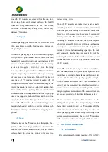
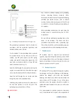
Fig. 7 Diagram of the bolt installation process 


Place the PV module on top of the rack. 


Insert  4  stainless  steel  bolts  in  corresponding 

mounting  holes.  The  9x14mm  mounting  holes 

match with M8 bolts, while the 7x10mm mounting 

holes  match  with  M6  bolts.  7x10mm  mounting 

holes are positioned with a hole pitch of 400mm. 


Make  sure  to  use  two  stainless  steel  washers  for 

each bolt, one on each side of the rack. Then screw 

on  the  top  of  a  stainless-steel  spring  washer  or 

toothed  lock  washer.  Finally,  lock  with  a 

stainless-steel nut. 


The  tightening  torque  is  recommended  to  be 

9~12Nm for M6 bolts and 17~23Nm for M8 bolts. 

Due to the possible difference of bolt material, the 

specific  torque  value  is  subject  to  the  information 

confirmed by the bolt supplier.


5.3.2


Clamped mounting 

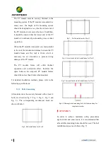
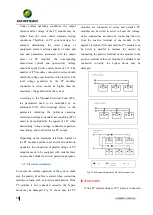
Photovoltaic  modules  can  be  installed  across  the 

support  frame  (Fig.  8)  or  parallel  to  the  frame  of  the 

photovoltaic  module  (Fig.  9).  When  using  clamps  to 

install, each module must be secured with a minimum 

of 4 clamps.


Fig. 8 Rails overlapping the long-side frame 


Fig. 9 Rails overlapping the short-side frame 

ATTENTION


The length of the rack must be longer than the PV 

module, otherwise it should be confirmed by Chint 

Solar in advance. 


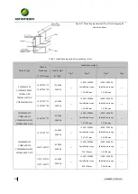
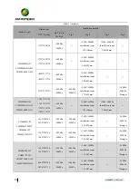
The  above  two  diagrams  show  the  mounting 

method  using  aluminum  clamps.  "D"  indicates  the 

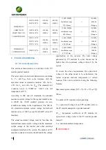
mounting  range.  Table  1  shows  the  recommended 

mounting  position  and  corresponding  machine 

loads. 


Each aluminum clamp is equipped with an M8 bolt, 

a flat washer, a spring washer and an M8 nut. The 

mounting steps are as follows:


Place  the  module  on  the  two  supporting  rails  (not 

provided  by  Chint)  which  should  be  made  with 

stainless material and treated with an anti-corrosion 

process  (e.g.  hot  dipped  galvanizing).  Each  PV 

module needs at least four clamps to be fixed. The 

module  clamps  should  not  come  into  contact  with 

Summary of Contents for CHSM54M(BL)-HC

Page 1: ...1 Crystalline Silicon PV Module Installation Manual...

Page 2: ...1 Transport 6 4 2 Unpack 7 4 3 Stack 7 5 Mechanical installation 7 5 1 Environment 7 5 2 Tilt angle selection 8 5 3 Mounting Guide 8 5 3 1 Bolted mounting 9 5 3 2 Clamped mounting 10 6 Electrical Inst...

Page 3: ...ed with is beyond the control of Chint Solar Chint shall not be liable for any form of loss including but not limited to loss damage casualty or additional cost caused by improper installation operati...

Page 4: ...a or PV module storage area It is forbidden to install or use damaged PV modules It is forbidden to repair PV modules by unauthorized personnel including but not limited to replacing any part of PV mo...

Page 5: ...and be aware of bumps in the corners When installing or repairing the PV system do not wear any metal accessories to avoid the risk of electric shock if it is installed far above the ground please we...

Page 6: ...connector or make electrical connections in any other way 4 Handling and unpacking If the PV module is not in use please do not open the product packaging The goods should be stored in a dark dry and...

Page 7: ...from colliding and scratching with the cement surface hard object on the ground color steel tile metal corrugated etc When the PV modules are stacked they must be neatly and stably stacked on a horiz...

Page 8: ...tion The tilt angle of a PV module refers to the angle between the surface of the PV module and the ground surface as shown in Fig 1 The power output of a PV module is maximized when it faces the sun...

Page 9: ...raction effect therefore the space between two adjacent PV module frames should be no less than 10mm when mounted For detailed installation methods please refer to the following specifications 5 3 1 B...

Page 10: ...e installed across the support frame Fig 8 or parallel to the frame of the photovoltaic module Fig 9 When using clamps to install each module must be secured with a minimum of 4 clamps Fig 8 Rails ove...

Page 11: ...shown in Fig 10 and the fringe clamp shown in Fig 11 and Fig 12 The mid clamp has dimensions of a 40 mm b 26 mm c 5 mm d 28 mm 9 mm For module of 182mm wafer the size of mid and fringe clamp must mee...

Page 12: ...00Pa 2400Pa 5400 2400Pa Installation scope 198 408mm 2400 2400Pa Installation scope 50 200mm CHSM60M HC CHSM60P HC CHSM60M BL HC CHSM60M LV HC 1666 992 35 5400Pa 2400Pa 5400 2400Pa Installation scope...

Page 13: ...M HC CHSM54M BL HC CHSM54M LV HC 1708 1133 30 1708 1133 35 1722 1134 30 1722 1134 35 5400Pa 2400Pa 5400 2400Pa Installation scope 359 50mm 1400 1400Pa Installation scope 200 50mm CHSM6612M CHSM6612M H...

Page 14: ...m voltage for the regular module series is 1000V the 1500V standard products are also available according to the requirements The IEC UL standard maximum system voltage for half cell module series is...

Page 15: ...ge ratings conductor capacities fuse ratings and control sizes for PV output Depending on the maximum rated fuse current of the PV module and the local electrical installation standards the connection...

Page 16: ...ng connectors to direct sunlight and soaking in water Avoid the connectors falling on the ground or the roof Do not plug or unplug the connectors when the PV module is in live state When it is necessa...

Page 17: ...that meet the requirements of UL 467 and is suitable for electrical bonding and grounding of PV modules Other grounding methods may be used when the racking system is tested following the UL 2703 req...

Page 18: ...it is generally not necessary to clean the PV module as the rainfall will provide a self cleaning effect If there is a large accumulation of dirt on the PV module surface that has seriously affected t...

Page 19: ...released in June 2018 Rev 1 1 released in July 2020 Rev 1 2 released in October 2021 CHINT SOLAR ZHEJIANG Co Ltd Add 1335 Bin an Rd Binjiang District Hangzhou China 310053 Tel 86 571 5603 1888 Fax 86...

Reviews: