background image

Illustrations

Illustrations

2

Electronic equipment is not household waste – in accordance
with directive 2002/96/EC OF THE EUROPEAN PARLIA-
MENT AND THE COUNCIL of 27th January 2003 on used
electrical and electronic equipment, it must be disposed of
properly. At the end of its service life, take this unit for dispo-
sal at a relevant official collection point.


Summary of Contents for XX-A/V quad

Page 1: ...X X A V quad Audio Video Modulator Card Operating Instructions ...

Page 2: ... accordance with directive 2002 96 EC OF THE EUROPEAN PARLIA MENT AND THE COUNCIL of 27th January 2003 on used electrical and electronic equipment it must be disposed of properly At the end of its service life take this unit for dispo sal at a relevant official collection point ...

Page 3: ...ed via the HE programming software or the KC 3 handheld programming device The X A V quad can only be used in combination with the V16 and X 8 twin base units as these have the necessary moun ting hardware for the input jacks a full complement of X A V quads can only be installed in combination with the V16 13 X 8 twin base unit otherwise a maximum of only two X A V units is possible The video sig...

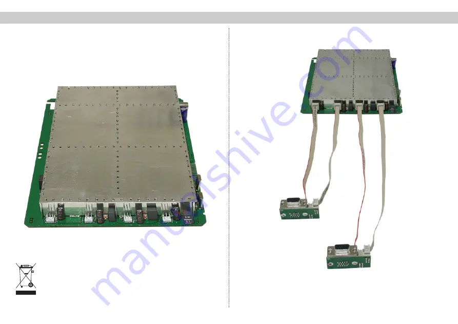
Page 4: ...r base units than those listed above Remove the covers from the base device plug in card slot and insert the supplied female connectors Check that the post connectors are correctly positioned on the plug in card and on the adapter PCB 2 Installation and connection 2 Installation and connection 4 Insert the plug in card and push on the post connectors observe the correct orienta tion V16 13 X 8 ...

Page 5: ... software After the base unit has been read out the overview window of the base unit will show the X A V quad card on the slot on which it is installed 2 2 Connection of source devices A VCP 15 2 connecting cable order no 350151 1 4 m is required in order to connect an A V audio source device such as a DVD player camera etc The cable has a 15 pole Sub D connector at one end and 2x 3 way Cinch RCA ...

Page 6: ...u can activate or deactivate the output channel and define the audio mode Stereo Mono or 2 channel The output channel is also defined at this point Please note that by defining the A channel for a pair of chan nels you are also defining the B channel as its adjacent channel The allocation of output channels is shown in the Channel Overview window Double click in this window to switch between the c...

Page 7: ...ups 1 Start menu The software version number is displayed Please quote this version number whenever contac ting our customer service department The Start menu can only be accessed again later on by unplugging and replugging the KC 3 2 Programming the channel specific parameters The channel specific parameters are programmed in two menus Line 1 Menu Select plug in card slot channel group Lines 3 4 ...

Page 8: ...keys to change the audio mode You can choose from Mono Stereo or 2 channel sound Press the Menu Read button again to go to Activation and deactivation of the output signal Use the or cursor keys to activate or deactivate the output signal 4 2 Moving between menus Use the and arrow keys to change between rows Press the MENU button to change between sub menus in a row 4 3 Entering parameters Enter v...

Page 9: ... Pin 1 audio left Pin 2 GND Pin 3 video Pin 4 not used Pin 5 audio right Pin 6 GND Press the Menu Read button repeatedly to go to the Error messages In the event of a hardware fault on the plug in card or channel group an error code is output here Please contact our customer service department if this hap pens Setting the output level On the X A V quad the level is equalized electronically The RF ...

Page 10: ...60 Active return loss dB 10 Signal to spurious emission ratio dB typ 60 TV standard B G Video signal to noise ratio dB typ 54 overall device Audio Video Input 15 pole SUB D socket 2x A V input signals per socket Audio Input level V RMS 0 5 10 kΩ Frequency range 40 Hz 15 kHz Noise level distance dB typ 45 Video Bandwidth 25 Hz 4 8 MHz Input level 1 Vss 75 Ω Common data Ambient temperature C 0 50 ...

Page 11: ...n the submenus 04 AV Quad A OK BildTr 471 2 MHz Channel C21 01 Slot no or unknown Plug in Card with Menu Read key switch between the submenus 04 AV Quad A OK BildTr 471 2 MHz Channel C21 V16 Serie Password 0000 Password OK Menu New PW xxxx V16 Setup VMS 616 yes Power A B Password off with Cursorbuttons or to Menu 1 ASTRO V16 Version 1 19 1 deutsch next Choose line 3 with Cursorkeys or Choose line ...

Page 12: ...ASTRO Strobel Kommunikationssysteme GmbH Olefant 1 3 D 51427 Bergisch Gladbach Bensberg Tel 0 22 04 405 0 Fax 0 22 04 405 10 http www astro kom de 82 319 400 10 06 GB ...

Reviews: