


13
GND
COM
NO
GND
485A
485B
232TX
232RX
GND
+12V
8
7
6
5
4
3
2
1
L
I
A
H
N
2.8
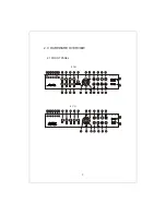
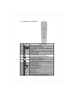
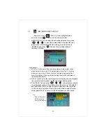
Alarm Input and Output
There are 8 sets alarm input connector and 1 set output for this DVR.
Alarm input is for connection IR annunciator, fog sensor.
The connection diagram of DC alarm input as following:
2.7 Connectors for Alarm
Peel off the color skin of the cable and then insert the cable into
the slot on the rear panel DVR (The connection part for alarm).
Example 1 : From contact alarm input connections into a camera
passive infrared detectors
Example 2 : Connect alarm dry contact output to alarm normally open N.O
GND
COM
NO
GND
485A
485B
232TX
232RX
GND
+12V
8
7
6
5
4
3
2
1
A
L
H
I
N
GND
GND
COM
NO
GND
485A
485B
232TX
232RX
GND
+12V
8
7
6
5
4
3
2
1
A
L
H
I
N
Com
ALH IN
GND
COM
N.O
485A
485B
232TX
232RX
GND
+12V
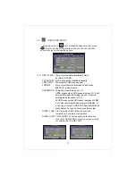
Alarm 1~8 (4) Camera Alarm Input
Grounding
Alarm contact common ground
Alarm output normally open contact
RS-485 Send + Connect to PTZ
RS-485 Send - Connect to PTZ
RS-232 Send +
For connecting PC
RS-232 Send -
For connecting PC
Power Dc-12v Output Grounding
Power Dc+12v Output (500mA Max)
GND
RS-485 ,RS-232 contact common ground


