16 1-800-810-WIRE • www.sargentlock.com • A8032D
Copyright © 2010, Sargen
t Manufacturing Company
, an A
SS
A AB
LO
Y G
roup company
. All right
s reser
ved
.
Reproductions in whole or in par
t without express writ
ten permission of Sargen
t Manufacturing Company is prohibited
.
12/15/10
Passport 1000 Series P1 PoE Mortise Lock
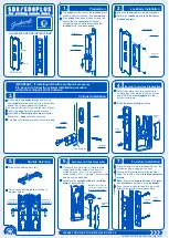
9 Install Inside Module Component Assembly
Insert bottom of Module Component Assembly first (Fig.
9A), then clip top of Assembly to backplate, verifying
both tabs attached securely.
Outside of Door
Fig. 9A
Tabs
Detail 10B
(2) 4-Pin PoE
connectors
e
d
b
c
24-pin from reader
10-pin from lock body
e
d
c
b
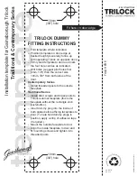
10 Attach Connectors
Secure the following connectors onto the circuit board (Fig.
10A and 10B):
1. Secure the 10-pin lock body assembly connector (e).
2. Secure the 24-pin keypad/card reader connector (d).
3. Secure two 4-pin PoE connectors (b and c).
4. Secure the iCLASS reader cable (f).
Route wires from behind backplate through battery com-
partment.
Notes:
• Connectors go on only one way.
• Do not force and do not offset connectors.
• Be sure the connectors are completely seated (flush).
f
9-pin reader cable (iCLASS only)
f
PRELIMINARY