40
The warranty on Corbin Russwin products becomes void if the product is modified in any way, regardless of whether the modifications causes or contributes to any alleged defect. If a
Corbin Russwin product is modified it may no longer meet industry certification and quality control standards applicable to the original product and is no longer a genuine Corbin Russwin product.
Copyright © 1999-2018, ASSA ABLOY Access and Egress Hardware Group, Inc. All rights reserved. Reproduction in whole or in part without the express written permission of ASSA ABLOY Access
and Egress Hardware Group, Inc. is prohibited. Patent pending and/or patent www.assaabloydss.com/patents.
Service Procedures
UT5200 Parts Manual
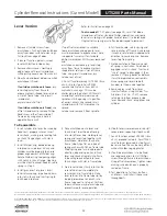
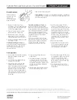
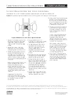
6. Before proceeding, make mental note of chassis orientation
relative to parts already laid out. Use ribbed wall as
reference point and remember whether it faced left or right
All functions except UT5210 and UT5282 have a spindle
which passes through chassis tube from one side, continues
through various hubs and spacers in center of chassis and
continues outward through opposite chassis tube. Parts vary
by function and so does direction of spindle removal.
Carefully tilt chassis to look into each end of tube and
determine which end of spindle is smaller. Hold chassis
so small end of spindle points upward. If spindle falls out
bottom tube at this to point, lay it out with other parts on
proper side of work space and proceed to step7. Otherwise,
look for small pin through hole in end of spindle.
Push spindle up from bottom until small pin can be removed
through hole in chassis tube. Caution! Cover top end of
tube during this process. Some functions have parts which
spring off spindle when pin is removed. Spindle should now
drop out. If not, gently rotate it until it falls out. Lay spindle
and all other parts out in order on proper side(s) of work
space.
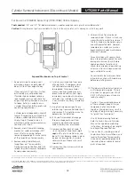
7. Observe order and orientation of hubs and spacers inside
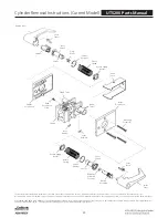
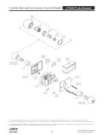
chassis. Consult exploded view page for reference. Depress
main latch to allow hubs to fall out. Again, lay them out
carefully in center of work space from left to right as
originally installed. Disassembly is now complete.
8. Turn chassis over so opposite tube points up. Depress main
latch and reload hubs in same order as removed. Refer to
appropriate exploded view page if parts get mixed. Caution:
if any hub has a rectangular or “double-D” hole, its
orientation is critical. Diagonal flats of hole must face holes
in latch tube.
9. Install small end of spindle from bottom, passing through all
hubs. If spindle has flat sides, verify that hole in spindle faces
holes in frame tube. If not, Step 8 was incorrect.
10. Supporting spindle with finger in bottom tube, reinstall
other parts (
depending on function
) over top end of
spindle. In the case of some spring loaded assemblies, use
small screwdriver to depress assembly into the chassis far
enough to clear hole in end of spindle. Insert retainer pin
through frame tube hole and install into spindle.
Before proceeding, check orientation of all parts in chassis
against exploded view page. For comparison, all pages
illustrate left hand reverse bevel assembly.
11. Remembering original left to right orientation of chassis
on work space, turn chassis upside down so knobs and
escutcheons are ready to install on opposite sides from
original orientation. Note: Opposite escutcheon now
becomes fixed (
always attached to ribbed wall of chassis
).
Only small screw and washer must switch sides at this
point. These must enter from other side of chassis for
reassembly.
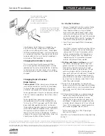
Observe sides of chassis and locate side with three vertical
ribs. Install trim on this side first.
12. Place circular wire retainer around frame tube, but do not
push all the way into position.
13. Put sleeve into back of knob and place that assembly
through hole in escutcheon. Slide knob into frame tube
as far as it will go. If this knob has cylinder, be sure top of
keyway points toward latch (
edge of door
). Groove around
the knob shank should now be positioned under the
retainer slot in the frame tube.
14. Install crescent knob retainer and move retainer ring into
place to secure crescent retainer.
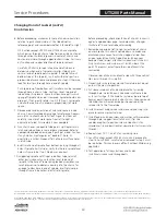
15. Install fixed escutcheon screw and washer with screwdriver
through hole in opposite wall of chassis. (Tip: Use
needlenose pliers to position screw inside chassis for
screwdriver tip and point lockset upward to start screw into
threads.)
16. Repeat steps 10, 11, and 12 for remaining side.
17. For all functions except UT5282 (
store door
), proceed to
step 18. For UT5282, small retainer removed in step 2 must
be reinstalled. This can be very difficult without Waldes ring
applicator.
18. Test operation of all keys, buttons and knobs.
Install chassis cover and throughbolts.
Changing Hand of Lockset (cont'd)
Knob Version


