


26
2.12 Onboard Headers and Connectors
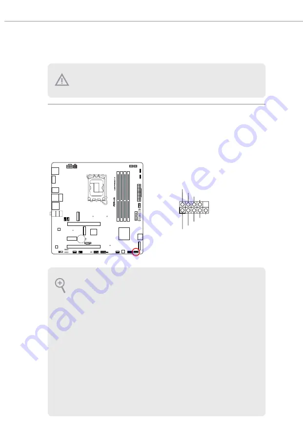
System Panel Header
(9-pin PANEL1) (see p.6, No. 15)
Connect the power button, reset button and system status indicator on the chassis
to this header according to the pin assignments below. Note the positive and
negative pins before connecting the cables.
Z
7
9
0
m
P
G
GND
RESET#
PWRBTN#
PLED-
PLED+
GND
HDLED-
HDLED+
1
GND
PANEL1
Onboard headers and connectors are NOT jumpers. Do NOT place jumper caps over these
headers and connectors. Placing jumper caps over the headers and connectors will cause
permanent damage to the motherboard.
PWRBTN (Power Button):
Connect to the power button on the chassis front panel. You may configure the way to turn
off your system using the power button.
RESET (Reset Button):
Connect to the reset button on the chassis front panel. Press the reset button to restart the
computer if the computer freezes and fails to perform a normal restart.
PLED (System Power LED):
Connect to the power status indicator on the chassis front panel. The LED is on when the
system is operating. The LED keeps blinking when the system is in S1/S3 sleep state. The
LED is off when the system is in S4 sleep state or powered off (S5).
HDLED (Hard Drive Activity LED):
Connect to the hard drive activity LED on the chassis front panel. The LED is on when the
hard drive is reading or writing data.
The front panel design may differ by chassis. A front panel module mainly consists of power
button, reset button, power LED, hard drive activity LED, speaker and etc. When connect-
ing your chassis front panel module to this header, make sure the wire assignments and the
pin assignments are matched correctly.
Summary of Contents for PHANTOM GAMING Z790M PC LIGHTNING/D4
Page 1: ......
Page 4: ...2 15 M 2 SSD Module Installation Guide M2_1 42 2 16 M 2 SSD Module Installation Guide M2_2 44 ...
Page 17: ...13 Z790M PG Lightning D4 2 2 Installing the CPU Fan and Heatsink 1 2 C P U _ F A N ...
Page 19: ...15 Z790M PG Lightning D4 1 2 3 ...
Page 21: ...17 Z790M PG Lightning D4 2 5 Installing the Motherboard Z790m PG ...
Page 22: ...18 2 6 Installing SATA Drives 1 2 Optical Drive SATA Drive SATA Data Cable ...
Page 23: ...19 Z790M PG Lightning D4 3 4 SATA Power Connector SATA Data Connector ...
Page 24: ...20 2 7 Installing a Graphics Card 1 CLICK ...
Page 26: ...22 2 8 Connecting Peripheral Devices ...
Page 27: ...23 Z790M PG Lightning D4 2 9 Connecting the Power Connectors 7 3 5 7 9 ...
Page 28: ...24 2 10 Power On 2 3 4 1 ...


