background image

English

46

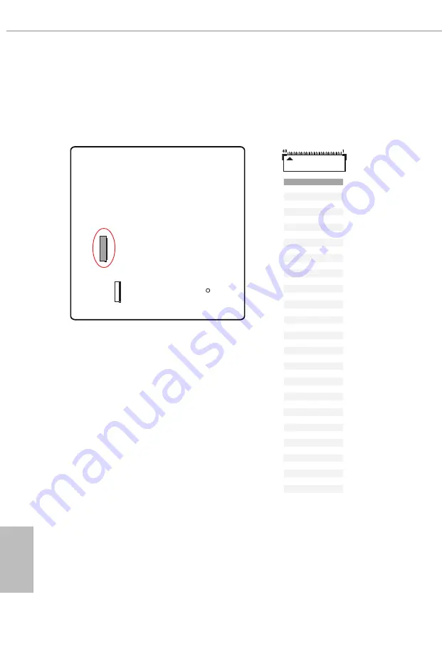
eDP Signal Connector
(40-pin EDP1) (see p.7, No. 18)
This connector on the bottom side of the motherboard is for an LCD monitor that 
supports an internal embedded DisplayPort (eDP). 
*Please refer to page 53 for further instructions on how to adjust the brightness.

PIN

SIGNAL

1

N/A

2

LCD_BLT_VCC

3

LCD_BLT_VCC

4

LCD_BLT_VCC

5

LCD_BLT_VCC

6

N/A

7

N/A

8

eDP_VARY_BL

9

eDP_BLON

10

BKT_GND

11

BKT_GND

12

BKT_GND

13

BKT_GND

14

eDP_HPD_CON

15

PNL_GND

16

PNL_GND

17

PNL_GND

18

PNL_GND

19

N/A

20

+LVDD

21

+LVDD

22

+LVDD

23

+LVDD

24

GND

25

eDP_AUX#_CON

26

eDP_AUX_CON

27

GND

28

eDP_TX0_CON

29

eDP_TX#0_CON

30

GND

31

eDP_TX1_CON

32

eDP_TX#1_CON

33

GND

34

N/A

35

N/A

36

GND

37

N/A

38

N/A

39

GND

40

N/A

Summary of Contents for PHANTOM GAMING B650E PG-ITX WiFi

Page 1: ......

Page 2: ... com or you may contact your dealer for further information For technical questions please submit a support request form at https event asrock com tsd asp ASRock Incorporation e mail info asrock com tw ASRock EUROPE B V e mail sales asrock nl ASRock America Inc e mail sales asrockamerica com Scan the QR code to view more manuals and documents ...

Page 3: ...nstalling the CPU 14 2 2 Installing the CPU Fan and Heatsink 17 2 3 Installing Memory Modules DIMM 26 2 4 Connecting the Front Panel Header 28 2 5 Installing the Motherboard 29 2 6 Installing SATA Drives 30 2 7 Installing a Graphics Card 32 2 8 Connecting Peripheral Devices 34 2 9 Connecting the Power Connectors 35 2 10 Power On 36 2 11 Jumpers Setup 37 2 12 Onboard Headers and Connectors 38 2 13 ...

Page 4: ...2 14 M 2 SSD Module Installation Guide M2_2 51 2 15 Change Screen Brightness for eDP in Windows 53 ...

Page 5: ... Data Cables Optional 1 x ASRock WiFi 2 4 5 6 GHz Antenna Optional 1 x Screw for M 2 Socket Optional Because the motherboard specifications and the BIOS software might be updated the content of this documentation will be subject to change without notice In case any modifications of this documentation occur the updated version will be available on ASRock s website without further notice If you requ...

Page 6: ... List on ASRock s website for more information http www asrock com Expansion Slot CPU 1 x PCIe 5 0 x16 Slot PCIE1 supports x16 mode Chipset 1 x Vertical M 2 Socket Key E supports type 2230 WiFi BT PCIe WiFi module Supports NVMe SSD as boot disks Graphics Integrated AMD RDNATM 2 graphics Actual support may vary by CPU 1 x eDP 1 4 supports max resolution up to Full HD 60Hz 1 x HDMI 2 1 TMDS FRL 8G C...

Page 7: ...available A 6GHz compatible router is required for 6E functionality 2 antennas to support 2 Transmit x 2 Receive diversity technology Supports Bluetooth High speed class II Supports MU MIMO Supports Killer LAN Software Supports Killer DoubleShotTM Pro USB 1 x USB 3 2 Gen2x2 Type C Front 1 x USB 3 2 Gen2 Type C Rear 3 x USB 3 2 Gen2 Type A Rear 2 x USB 3 2 Gen1 Front 6 x USB 2 0 4 Rear 2 Front All ...

Page 8: ...ctor 2 x Addressable LED Headers 1 x CPU Fan Connector 4 pin 1 x CPU Water Pump Fan M 2 Fan Connector 4 pin Smart Fan Speed Control 1 x Chassis Water Pump Fan Connector 4 pin Smart Fan Speed Control 1 x 24 pin ATX Power Connector Hi Density Power Con nector 1 x 8 pin 12V Power Connector Hi Density Power Connec tor 1 x Front Panel Audio Connector 15μ Gold Audio Connec tor 1 x USB 2 0 Header Support...

Page 9: ...it 11 64 bit Certifica tions FCC CE ErP EuP ready ErP EuP ready power supply is required Please realize that there is a certain risk involved with overclocking including adjusting the setting in the BIOS applying Untied Overclocking Technology or using third party overclocking tools Overclocking may affect your system s stability or even cause damage to the components and devices of your system It...

Page 10: ...English 6 1 3 Motherboard Layout Top Side View ...

Page 11: ...English 7 B650E PG ITX WiFi Back Side View ...

Page 12: ...IMM Slots DDR5_A1 DDR5_B1 7 ATX Power Connector ATXPWR1 8 SATA3 Connector SATA3_2 9 SATA3 Connector SATA3_1 10 USB 3 2 Gen1 Header USB32_4_5 11 System Panel Header PANEL1 12 USB 2 0 Header USB_5_6 13 Front Panel Type C USB 3 2 Gen2x2 Header USB32_TC2 14 Clear CMOS Jumper CLRCMOS1 15 Chassis Water Pump Fan Connector CHA_FAN1 WP 16 Chassis Speaker Header SPEAKER1 17 Front Panel Audio Header HD_AUDIO...

Page 13: ...ype A Port USB32_1 5 Antenna Ports 10 USB 3 2 Gen2 Type C Port USB32_TC1 ACT LINK LED SPEED LED LAN Port There are two LEDs on each LAN port Please refer to the table below for the LAN port LED indications Activity Link LED Speed LED Status Description Status Description Off No Link Off 10Mbps connection Blinking Data Activity Orange 100Mbps 1Gbps connection On Link Green 2 5Gbps connection 5 6 8 ...

Page 14: ...7 1 channel Configuration Channel Port Function 2ch Line Out Jack Rear Panel Front speaker out 4ch Pink Mic Front Panel Rear speaker out 5 1ch Microphone Input Jack Rear Panel Central Subwoofer speaker out 7 1ch Lime Headphone Front Panel Side Speaker out ...

Page 15: ...ront USB 2 0 2 ports Rear USB 3 2 Gen2 2 ports Front USB 3 2 Gen2x2 Type C Front USB 3 2 Gen1 2 ports USB3 2 G1 x1 WiFi key E x1 Intel Killer E3100G USB3 2 G2x2 5Gb s 480Mb s USB2 0 PCIe GEN3 PCIe GEN3 USB3 2 G2 10Gb s DP2 HDMI Port PCIe Gen4 x4 M 2_2 PCIe x4 PCIe Gen5 x16 SIO NCT6686D AZ HD Audio Audio Codec ALC1220 2 1 Rear USB 3 2 Gen2 Type C USB3 2 G2 10Gb s Rear USB 2 0 4 ports 480Mb s USB2 0...

Page 16: ...atures Smart Ready technology that adds a whole new class of functionality into the mobile devices BT also includes Low Energy Technology and ensures extraordinary low power consumption for PCs The transmission speed may vary according to the environment Wi Fi 6E 6GHz band will be supported by Microsoft Windows 11 The availability will depend on the different regulation status of each country and ...

Page 17: ...o may cause physical injuries and damages to motherboard components In order to avoid damage from static electricity to the motherboard s components NEVER place your motherboard directly on a carpet Also remember to use a grounded wrist strap or touch a safety grounded object before you handle the components Hold components by the edges and do not touch the ICs Whenever you uninstall any component...

Page 18: ...f the CPU surface is unclean or if there are any bent pins in the socket Do not force to insert the CPU into the socket if above situation is found Otherwise the CPU will be seriously damaged 2 Unplug all power cables before installing the CPU Tutorial Video Turn your CPU to the correct orientation before opening the CPU socket cover ...

Page 19: ...English 15 B650E PG ITX WiFi Carefully place the CPU in as flat as possible Do not drop it 4 1 2 A B 3 ...

Page 20: ...removed The cover must be placed if you wish to return the motherboard for after service Make sure the black cover plate is always in place until it pops off when closing the socket lever Make sure the CPU is aligned with the socket before locking it into place ...

Page 21: ...tsink and cooling fan to dissipate heat You also need to spray thermal grease between the CPU and the heatsink to improve heat dissipation Make sure that the CPU and the heatsink are securely fastened and in good contact with each other Installing the CPU Cooler Type 1 Please turn off the power or remove the power cord before changing a CPU or heatsink 2 1 ...

Page 22: ...English 18 4 3 C P U _ F A N 1 ...

Page 23: ...English 19 B650E PG ITX WiFi Installing the CPU Cooler Type 2 2 1 ...

Page 24: ...English 20 3 4 C P U _ F A N 1 ...

Page 25: ...English 21 B650E PG ITX WiFi 5 C P U _ F A N 1 RG B_LED1 The illustrations shown here are for reference purposes only and may not exactly match the model you purchase 12V ...

Page 26: ...English 22 Installing the CPU Cooler Type 3 2 1 ...

Page 27: ...English 23 B650E PG ITX WiFi 4 3 ...

Page 28: ...English 24 5 C P U _ F A N 1 ...

Page 29: ...e cable should be used at a time in this step If you select RGB_LED1 please install ASRock utility ASRock Polychrome SYNC If you select USB connector please install AMD utility SR3 Settings Software The illustrations shown here are for reference purposes only and may not exactly match the model you purchase 12V or ...

Page 30: ...el configuration you always need to install identical the same brand speed size and chip type DDR5 DIMM pairs 2 It is unable to activate Dual Channel Memory Technology with only one memory module installed 3 It is not allowed to install a DDR DDR2 DDR3 or DDR4 memory module into a DDR5 slot otherwise this motherboard and DIMM may be damaged 4 The DIMM only fits in one correct orientation It will c...

Page 31: ...English 27 B650E PG ITX WiFi 1 2 3 ...

Page 32: ...cting the Front Panel Header A B C D 1 2 32 5 6 5 6 7 6 3 2 5 3 2 5 3 1 Power SW RESET SW HDD LED HDD LED 1 2 9 10 RESET SW Power SW Power LED Power LED A B C D PANEL1 HDD LED RESET SW System Panel Header Front Panel Wires ...

Page 33: ...English 29 B650E PG ITX WiFi 2 5 Installing the Motherboard ...

Page 34: ...English 30 2 6 Installing SATA Drives 1 2 Optical Drive SATA Drive SATA Data Cable ...

Page 35: ...English 31 B650E PG ITX WiFi 3 4 SATA Power Connector SATA Data Connector ...

Page 36: ...English 32 2 7 Installing a Graphics Card 1 CLICK ...

Page 37: ...PCIe 5 0 x16 slot is used for PCIe x16 lane width graphics cards Before installing an expansion card please make sure that the power supply is switched off or the power cord is unplugged Please read the documentation of the expansion card and make necessary hardware settings for the card before you start the installation ...

Page 38: ...English 34 2 8 Connecting Peripheral Devices ...

Page 39: ...English 35 B650E PG ITX WiFi 2 9 Connecting the Power Connectors 7 3 5 7 9 ...

Page 40: ...English 36 2 10 Power On 2 3 4 1 ...

Page 41: ...etup information such as system password date time and system setup parameters To clear and reset the system parameters to default setup please turn off the computer and unplug the power cord then use a jumper cap to short the pins on CLRCMOS1 for 3 seconds Please remember to remove the jumper cap after clearing the CMOS If you need to clear the CMOS when you just finish updating the BIOS you must...

Page 42: ...n the chassis front panel Press the reset button to restart the computer if the computer freezes and fails to perform a normal restart PLED System Power LED Connect to the power status indicator on the chassis front panel The LED is on when the system is operating The LED keeps blinking when the system is in S1 S3 sleep state The LED is off when the system is in S4 sleep state or powered off S5 HD...

Page 43: ... No 9 SATA3_2 see p 6 No 8 These two SATA3 connectors support SATA data cables for internal storage devices with up to 6 0 Gb s data transfer rate SATA3_1 SATA3_2 Status Description Blinking 2Hz Booting into system On Booting completed Blinking till BFG DRAM overclocking failed On Booting without DRAM Blinking 1Hz Entering S3 sleep mode ...

Page 44: ...s USB 3 2 Gen1 Header 19 pin USB32_4_5 see p 6 No 10 There is one header on this motherboard This USB 3 2 Gen1 header can support two ports USB32_4_5 1 IntA_PB_D Dummy IntA_PB_D GND IntA_PB_SSTX GND IntA_PB_SSTX IntA_PB_SSRX IntA_PB_SSRX Vbus Vbus IntA_PA_SSRX IntA_PA_SSRX GND IntA_PA_SSTX IntA_PA_SSTX GND IntA_PA_D IntA_PA_D USB_5_6 ...

Page 45: ...SB 3 2 Gen2x2 ports Front Panel Audio Header 9 pin HD_AUDIO1 see p 6 No 17 This header is for connecting audio devices to the front audio panel USB32_TC2 USB Type C Cable HD_AUDIO1 J_SENSE OUT2_L MIC_RET PRESENCE GND OUT2_R MIC2_R MIC2_L OUT_RET 1 High Definition Audio supports Jack Sensing but the panel wire on the chassis must support HDA to function correctly Please follow the instructions in o...

Page 46: ...sis Water Pump Fan Connector 4 pin CHA_FAN1 WP see p 6 No 15 This motherboard provides a 4 Pin water cooling chassis fan connectors If you plan to connect a 3 Pin chassis water cooler fan please connect it to Pin 1 3 CHA_FAN1 WP GND FAN_VOLTAGE CHA_FAN_SPEED FAN_SPEED_CONTROL 1 2 3 4 SPEAKER1 DUMMY SPEAKER 1 DUMMY 5V ...

Page 47: ... see p 6 No 5 This motherboard provides a 4 Pin water cooling CPU fan connector If you plan to connect a 3 Pin CPU water cooler fan please connect it to Pin 1 3 CPU_FAN2 WP M 2 fan connector is connected to the attached fan cable of ASRock Blazing M 2 Gen5 Fan Heatsink pre installed on M2_1 socket Please refer to page 47 for details CPU_FAN1 CPU_FAN2 WP 4 3 2 1 GND 12V CPU_FAN_SPEED FAN_SPEED_CONT...

Page 48: ...1 and Pin 13 ATX 12V Power Connector 8 pin ATX12V1 see p 6 No 1 This motherboard provides a 8 pin ATX 12V power connector To use a 4 pin ATX power supply please plug it along Pin 1 and Pin 5 Warning Please make sure that the power cable connected is for the CPU and not the graphics card Do not plug the PCIe power cable to this connector ATX12V1 4 1 8 5 ATXPWR1 12 1 24 13 ...

Page 49: ...able LED Headers ADDR_ LED1 ADDR_LED2 on the motherboard VOUT DO_ADDR GND 1 ADDR_LED2 VOUT DO_ADDR GND 1 ADDR_LED1 1 Never install the RGB LED cable in the wrong orientation otherwise the cable may be damaged 2 Before installing or removing your RGB LED cable please power off your system and unplug the power cord from the power supply Failure to do so may cause dam ages to motherboard components 1...

Page 50: ... adjust the brightness PIN SIGNAL 1 N A 2 LCD_BLT_VCC 3 LCD_BLT_VCC 4 LCD_BLT_VCC 5 LCD_BLT_VCC 6 N A 7 N A 8 eDP_VARY_BL 9 eDP_BLON 10 BKT_GND 11 BKT_GND 12 BKT_GND 13 BKT_GND 14 eDP_HPD_CON 15 PNL_GND 16 PNL_GND 17 PNL_GND 18 PNL_GND 19 N A 20 LVDD 21 LVDD 22 LVDD 23 LVDD 24 GND 25 eDP_AUX _CON 26 eDP_AUX_CON 27 GND 28 eDP_TX0_CON 29 eDP_TX 0_CON 30 GND 31 eDP_TX1_CON 32 eDP_TX 1_CON 33 GND 34 N...

Page 51: ...zing M 2 Gen5 Fan Heatsink pre installed on M2_1 socket which is a M 2 SSD heatsink with fan that enables PCIe Gen5 SSD to achieve optimal heat dissipation ASRock Blazing M 2 Gen5 Fan Heatsink Dimension 94 5 23 0 35 3mm Fan Speed 12000 rpm Installing the M 2 SSD Module Step 1 Prepare a M 2 SSD module and the screw Step 2 Depending on the PCB type and length of your M 2 SSD module find the correspo...

Page 52: ... M 2 Gen5 Fan Heatsink Please remove the protective films on the bottom side of Blazing M 2 Gen5 Fan Heatsink before you install a M 2 SSD module Step 4 Align and gently insert the M 2 SSD module into the M 2 slot Please be aware that the M 2 SSD module only fits in one orientation A A 20o 2 1 1 ...

Page 53: ...notch on the SSD to the standoff on the motherboard otherwise the SSD module may be damaged Correct Installation The SSD s PCB is in proper place and Blazing M 2 Gen5 Fan Heatsink can be screwed in Incorrect Installation The SSD s PCB sits between Blazing M 2 Gen5 Fan Heatsink and standoff Do not continue ...

Page 54: ... module and Blazing M 2 Gen5 Fan Heatsink into place in the order shown Tighten screw opposite the M 2 connector first 2 and then tighten the one next to the M 2 connector 3 Please do not overtighten the screw as this might damage the module and Blazing M 2 Gen5 Fan Heatsink Step 7 Plug the attached fan cable to M 2 fan connector CPU_FAN2 WP see p 6 No 5 on the motherboard 1 2 3 ...

Page 55: ...replace mPCIe and mSATA The Hyper M 2 Socket M2_2 Key M supports type 2280 PCIe Gen4x4 64 Gb s mode Installing the M 2 SSD Module Step 1 Prepare a M 2 SSD module and the screw Step 2 Depending on the PCB type and length of your M 2 SSD module find the corresponding nut location to be used No 1 Nut Location A PCB Length 8cm Module Type Type 2280 ...

Page 56: ...lease be aware that the M 2 SSD module only fits in one orientation Step 4 Tighten the screw with a screwdriver to secure the module into place Please do not overtighten the screw as this might damage the module For the latest updates of M 2 SSD module support list please visit our website for details http www asrock com A A 20o NUT1 NUT2 ...

Page 57: ...reen brightness in Windows when you use an eDP panel Setup Guide Step 1 Right click on desktop Select Display settings Step 2 In System Display select Brightness Move the slider to fine tune the brightness level The following is a setup example for Windows 11 Setup procedures may vary from different operating systems ...

Page 58: ...h 54 Step 3 You might also see another check box displayed Help improve battery by optimizing the content shown and brightness Select the check box to turn on the content adaptive brightness control if needed ...

Page 59: ...ts loss of business loss of data interruption of business and the like even if ASRock has been advised of the possibility of such damages arising from any defect or error in the documentation or product This device complies with Part 15 of the FCC Rules Operation is subject to the following two conditions 1 this device may not cause harmful interference and 2 this device must accept any interferen...

Page 60: ...ornia Legislature When you discard the Lithium battery in California USA please follow the related regulations in advance Perchlorate Material special handling may apply see www dtsc ca gov hazardouswaste perchlorate AUSTRALIA ONLY Our goods come with guarantees that cannot be excluded under the Australian Consumer Law You are entitled to a replacement or refund for a major failure and compensatio...

Page 61: ...ock disclose the relevant information based on regulation requirements Please refer to https www asrock com general about asp cat Responsibility for informa tion disclosure based on regulation requirements ASRock is complied with DO NOT throw the motherboard in municipal waste This product has been designed to enable proper reuse of parts and recycling This symbol of the crossed out wheeled bin in...

Page 62: ...ransmit power per transceiver type Function Frequency Maximum Output Power EIRP WiFi 2400 2483 5 MHz 18 5 1 5 dbm 5150 5250 MHz 21 5 1 5 dbm 5250 5350 MHz 18 5 1 5 dbm no TPC 21 5 1 5 dbm TPC 5470 5725 MHz 25 5 1 5 dbm no TPC 28 5 1 5 dbm TPC Bluetooth 2400 2483 5 MHz 8 5 1 5 dbm ...

Reviews: