English
45
B650E PG-ITX WiFi
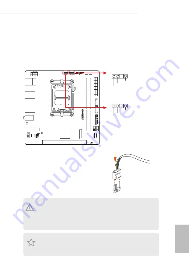
Addressable LED Headers
(3-pin ADDR_LED1) (see p.6, No. 2)
(3-pin ADDR_LED2) (see p.6, No. 3)
These headers are used to connect Addressable LED extension cables which allow users
to choose from various LED lighting effects.
Caution: Never install the Addressable LED cable in the wrong orientation; otherwise,
the cable may be damaged.
1
Connect your Addressable RGB LED strips
to the
Addressable LED Headers (ADDR_
LED1 / ADDR_LED2)
on the motherboard.
VOUT
DO_ADDR
GND
1
ADDR_LED2
VOUT
DO_ADDR
GND
1
ADDR_LED1
1. Never install the RGB LED cable in the wrong orientation; otherwise, the cable
may be damaged.
2. Before installing or removing your RGB LED cable, please power off your system
and unplug the power cord from the power supply. Failure to do so may cause dam-
ages to motherboard components.
1. Please note that the RGB LED strips do not come with the package.
2. The RGB LED header supports WS2812B addressable RGB LED strip (5V/Data/
GND), with a maximum power rating of 3A (5V) and length within 2 meters.
Summary of Contents for PHANTOM GAMING B650E PG-ITX WiFi
Page 1: ......
Page 10: ...English 6 1 3 Motherboard Layout Top Side View ...
Page 11: ...English 7 B650E PG ITX WiFi Back Side View ...
Page 22: ...English 18 4 3 C P U _ F A N 1 ...
Page 23: ...English 19 B650E PG ITX WiFi Installing the CPU Cooler Type 2 2 1 ...
Page 24: ...English 20 3 4 C P U _ F A N 1 ...
Page 26: ...English 22 Installing the CPU Cooler Type 3 2 1 ...
Page 27: ...English 23 B650E PG ITX WiFi 4 3 ...
Page 28: ...English 24 5 C P U _ F A N 1 ...
Page 31: ...English 27 B650E PG ITX WiFi 1 2 3 ...
Page 33: ...English 29 B650E PG ITX WiFi 2 5 Installing the Motherboard ...
Page 34: ...English 30 2 6 Installing SATA Drives 1 2 Optical Drive SATA Drive SATA Data Cable ...
Page 35: ...English 31 B650E PG ITX WiFi 3 4 SATA Power Connector SATA Data Connector ...
Page 36: ...English 32 2 7 Installing a Graphics Card 1 CLICK ...
Page 38: ...English 34 2 8 Connecting Peripheral Devices ...
Page 39: ...English 35 B650E PG ITX WiFi 2 9 Connecting the Power Connectors 7 3 5 7 9 ...


