ASROCK iBOX-210 User Manual Download Page 25

iBOX-210

21

English

4.4  Onboard Headers and Connectors
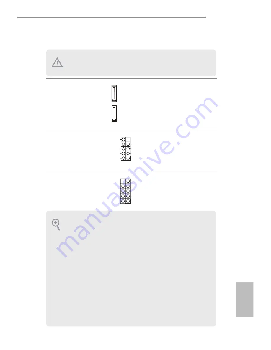
SATA2 Connectors 

(SATAII_1, SATAII_2) 

(see  p.15, No. 7)

hese two Serial ATA2  

(SATA2) connectors support  

SATA data cables for internal  

storage devices. he current  

SATA2 interface allows up to 

3.0 Gb/s data transfer rate.

USB 2.0 Headers 

(9-pin USB0_1, USB2_3, 

USB4_5)

(see p.15  No. 4)

here are three USB 2.0  

headers on this motherboard. 

System Panel Header 

(9-pin PANEL1) 

(see p.15  No. 11)

his header accommodates 

several system front panel   

functions.

DUMMY

GND

GND

+B

-B

+A

-A

USB_PWR

USB_PWR

1

GND

RESET#

PWRBTN#

PLED-

PLED+

GND

HDLED-

HDLED+

1

GND

SATAII_2

SATAII_1

Onboard headers and connectors are NOT jumpers. Do NOT place jumper caps over these 
headers and connectors. Placing jumper caps over the headers and connectors will cause 
permanent damage to the motherboard.

PWRBTN (Power Switch): 

Connect to the power switch on the chassis front panel. You may conigure the way to turn 
of your system using the power switch.

RESET (Reset Switch):


Connect to the reset switch on the chassis front panel. Press the reset switch to restart the 
computer if the computer freezes and fails to perform a normal restart.

PLED (System Power LED):


Connect to the power status indicator on the chassis front panel. he LED is on when the 
system is operating. he LED keeps blinking when the system is in S3 sleep state. he LED is 
of when the system is in S4 sleep state or powered of (S5).

HDLED (Hard Drive Activity LED):


Connect to the hard drive activity LED on the chassis front panel. he LED is on when the 
hard drive is reading or writing data.

he front panel design may difer by chassis. A front panel module mainly consists of power 
switch, reset switch, power LED, hard drive activity LED, speaker and etc. When connect-
ing your chassis front panel module to this header, make sure the wire assignments and the 
pin assignments are matched correctly.

Summary of Contents for iBOX-210

Page 1: ...iBOX 210 User Manual...

Page 2: ...lied including but not limited to the implied warranties or conditions of merchantability or itness for a particular purpose In no event shall ASRock its directors oicers employees or agents be liable...

Page 3: ...ORDING TO THE INSTRUCTIONS Contact Information If you need to contact ASRock or want to know more about ASRock you re welcome to visit ASRock s website at www ASRock com or you may contact your dealer...

Page 4: ...ving the Chassis Bottom Cover 8 3 2 Installing Memory Modules SO DIMM 9 3 3 Installing the 2 5 inch Hard Drive 10 3 4 Installing the WiFi module and the WiFi antennas Optional 12 3 5 Replacing the Cha...

Page 5: ...mini SATA slot M2x3 Power Adapter User Manual Because the hardware speciications might be updated the content of this documentation will be subject to change without notice In case any modiications o...

Page 6: ...22 1 x RS232 USB 2 USB 3 0 ports 2 USB2 0 ports LAN 1 RJ45 Port for Gbe Vedio output 1 x VGA output 1 x HDMI Audio Line out Expansion 1 x mini PCIe 1 x mSATA Storage Type 1 x 2 5 HDD SSD OS Support Wi...

Page 7: ...s 5Gbps 2 Rear USB3 0 ports SPI H W Monitor NCT6106D SATA2_2 SATAII Bus 480Mbps Asmedia USB 3 0 Hub ASM1074 PCIe x1 Mini PCIe eDP LVDS CPU FAN SYS FAN Audio Amplifier ALC109 CG ALC662 Audio Codec Line...

Page 8: ...pter 2 Product Overview his chapter provides diagrams showing the location of important components of the iBOX 210 2 1 Inside View Rear Panel Front Panel SO DIMM sockets M B mini PCIe mini SATA slot m...

Page 9: ...No Description 1 On of Switch 2 HDD LED 3 Power LED 4 2 x COM Ports 5 2 x USB 2 0 Ports Status LED Deinitions Power LED Status Description Solid Green Power on Of Power of HDD Status LED Status Descr...

Page 10: ...a Port 4 LAN RJ 45 Port LAN1 9 DC Jack DC IN 5 LAN RJ 45 Port LAN2 here are two LEDs on each LAN port Please refer to the table below for the LAN port LED indications Activity Link LED Speed LED Statu...

Page 11: ...Procedures Removing the chassis bottom cover Installing the memory modules SO DIMM Installing the 2 5 inch hard drive Installing the WiFi module and the WiFi antennas Optional Replacing the chassis to...

Page 12: ...8 English 3 1 Removing the Chassis Bottom Cover 1 Remove the four screws on the bottom case 2 Lit up and remove the top cover 1...

Page 13: ...M module into the DDR3_A2 for the irst priority 1 2 he SO DIMM only its in one correct orientation It will cause permanent damage to the motherboard and the SO DIMM if you force the SO DIMM into the s...

Page 14: ...the bottom cover with the printed circuit board side facing down Carefully align the mounting holes in the hard drive and the bottom cover 2 Secure the hard drive into the place using the four screws...

Page 15: ...iBOX 210 11 English 4 Attach the SATA data cable and power cable to the motherboard 4 SATAII_1 SATA Power Output Connector...

Page 16: ...e WiFi module and the WiFi antennas Optional 1 Insert the WiFi Module Card into the mini PCI Express slot MINI_PCIE1 2 Tighten the screw that holds the card in place 3 Attach the SMA Wi Fi Antenna Cab...

Page 17: ...sten the screw nuts to secure the antenna connectors 5 Connect the two WiFi 2 4 5 GHz Antennas to the antenna connectors Turn the antenna clockwise until it is securely connected 6 Set the WiFi 2 4 5...

Page 18: ...14 English 3 5 Replacing the Chassis Bottom Cover 1 Replace the top cover 2 Secure the four screws at the bottom 1 2...

Page 19: ...i PCIe 1 TPM1 PS2_KB_MS1 1 CHA_FAN1 SPEAKER1 1 LAN1 VGA1 Line Out HDMI1 ATX12V1 1 BLT_VOL1 HDLED RESET PLED PWRBTN PANEL1 1 mini PCIe mini SATA CI1 1 SATA_PWR1 LVDS1 1 1 BLT_PWR1 Industrial 1 SET_CM1...

Page 20: ...Control Level BLT_PWM1 10 3 Pin Chassis FAN Connector 11 System Panel Header 12 SATA Power Output Connector 13 Clear CMOS Header 14 Digital Input Output Pin Header 15 Digital Input Output Power Selec...

Page 21: ...ngle Channel DDR3L 1066 1333 MHz SDRAM Max 4GB Socket 1 x SO DIMM Graphics Controller Intel Gen7 Intel Graphics DX 11 OGL3 2 VRAM Shared Memory VGA Supports max resolution 1920 x 1200 LVDS Dual channe...

Page 22: ...AII_2 is shared with mSATA Parallel 0 IrDA 0 GPIO 8 bit 4 x GPI 4 x GPO SATA PWR Output Con 1 Speaker Header 1 Watchdog Timer Output From Super I O to drag RESETCON Interval 256 segments 0 1 2 255sec...

Page 23: ...MOS Jumper CLRCMOS1 see p 15 No 13 CLRCMOS1 allows you to clear the data in CMOS To clear and reset the system parameters to default setup please turn of the computer and unplug the power cord from th...

Page 24: ...CC 5 pin BKT_PWR1 see p 15 No 3 Use this to set up the backlight power of the LVDS connector 1 2 5V 2 3 12V 3 4 12V 4 5 DC_IN Power Backlight Control Level 3 pin BLT_PWM1 see p 15 No 9 1 2 3V 2 3 5V C...

Page 25: ...nect to the power switch on the chassis front panel You may conigure the way to turn of your system using the power switch RESET Reset Switch Connect to the reset switch on the chassis front panel Pre...

Page 26: ...15 No 2 Please connect a DC power sup ply 9V 36V to this connector 1 4 GND 2 3 DC Input SATA Power Output Connector 4 pin SATA_PWR1 see p 15 No 12 1 GND FAN_VOLTAGE CHA_FAN_SPEED GND 12V CHA_FAN_SPEE...

Page 27: ...422 485 on COM1 port Please refer to below table for the pin deinition In addition COM1 port RS232 422 485 can be adjusted in BIOS setup utility Advanced Screen Super IO Coniguration You may refer to...

Page 28: ...ND 26 GND 25 LVDS_B_ DATA1 28 LVDS_B_ DATA2 27 LVDS_B_ DATA2 30 LVDS_B_ DATA3 29 DPLVDD_EN 32 GND 31 LVDS_B_ DATA3 34 LVDS_B_CLK 33 LVDS_B_CLK 36 CON_LBKLT_ EN 35 GND 38 LCD_BLT_VCC 37 CON_LBKLT_ CTL...

Page 29: ...es platform integrity Chassis Intrusion Headers 2 pin CI1 CI2 see p 15 No 23 his motherboard supports CASE OPEN detection feature that detects if the chassis cover has been removed This feature requir...

Page 30: ...used for WiFi module mini PCIe mini SATA slot MINI_PCIE2 mini PCIe mini SATA slot full size is used for PCI Express mini cards or mSATA cards Before installing an expansion card please make sure that...

Reviews: