


6
66
66
1.2
1.2
1.2
1.2
1.2
Specifications
Specifications
Specifications
Specifications
Specifications
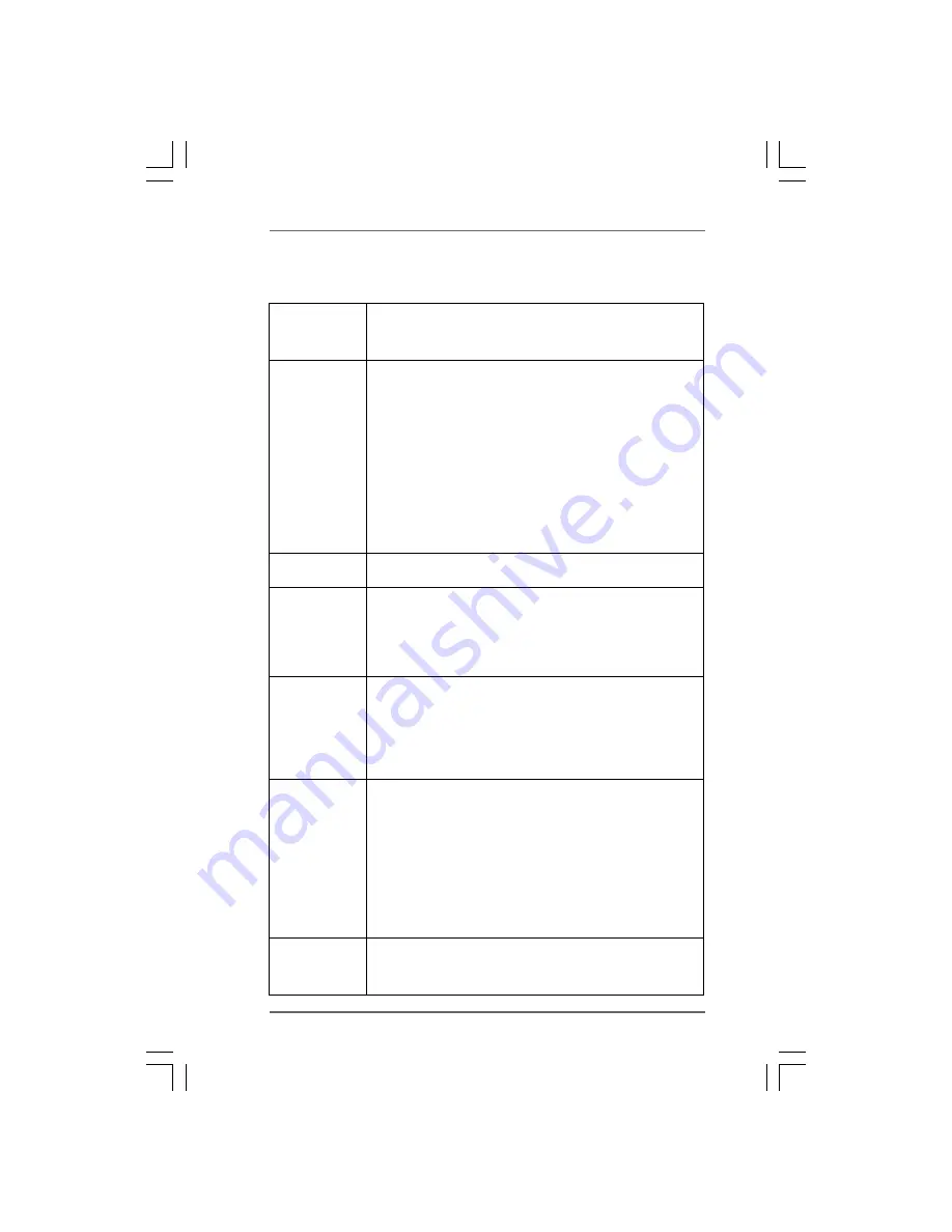
Platform
- ATX Form Factor: 12.0-in x 9.6-in, 30.5 cm x 24.4 cm
- All Solid Capacitor design (100% Japan-made high-quality
Conductive Polymer Capacitors)
CPU
- Support for Socket AM2+ / AM2 processors: AMD Phenom
TM
FX / Phenom / Athlon 64 FX / Athlon 64 X2 Dual-Core / Athlon
X2 Dual-Core / Athlon 64 / Sempron
processor
- Supports CPU up to 140W
- Supports AMD OverDrive
TM
with ACC feature
(Advanced Clock Calibration)
- AMD LIVE!
TM
Ready
- Supports AMD’s Cool ‘n’ Quiet
TM
Technology
- FSB 2600 MHz (5.2 GT/s)
- Supports Untied Overclocking Technology (see
CAUTION 1
)
- Supports Hyper-Transport 3.0 (HT 3.0) Technology
Chipset
- Northbridge: AMD 790GX
- Southbridge: AMD SB750
Memory
- Dual Channel DDR2 Memory Technology (see
CAUTION 2
)
- 4 x DDR2 DIMM slots
- Support DDR2 1066/800/667/533 non-ECC, un-buffered memory
(see
CAUTION 3
)
- Max. capacity of system memory: 8GB (see
CAUTION 4
)
Expansion Slot
- 2 x PCI Express 2.0 x16 slots
(green @ x16 mode, blue @ x8 mode)
- 1 x PCI Express 2.0 x1 slot
- 3 x PCI slots
- Supports ATI
TM
CrossFire
TM
and Hybrid CrossFireX
TM
(see
CAUTION 5
)
Graphics
- Integrated AMD Radeon HD 3300 graphics
- DX10 class iGPU, Pixel Shader 4.0
- Max. shared memory 512MB (see
CAUTION 6
)
- Integrated 128MB side port memory for iGPU
- Three VGA Output options: D-Sub, DVI-D and HDMI with
DVI-to-HDMI converter (see
CAUTION 7
)
- Supports HDCP function
- Supports Full HD 1080p Blu-ray (BD) / HD-DVD playback
(see
CAUTION 8
)
Audio
- 7.1 CH Windows
®
Vista
TM
Premium Level HD Audio with
Content Protection
- DAC with 110dB dynamic range (ALC890 Audio Codec)


