background image

Copyright © Askey, INC. All rights reserved.


12


Quick Installation Guide

Quick Installation Guide

Quick Installation Guide

Quick Installation Guide


EAI2001S Enterprise Access Point 

ENGLISH


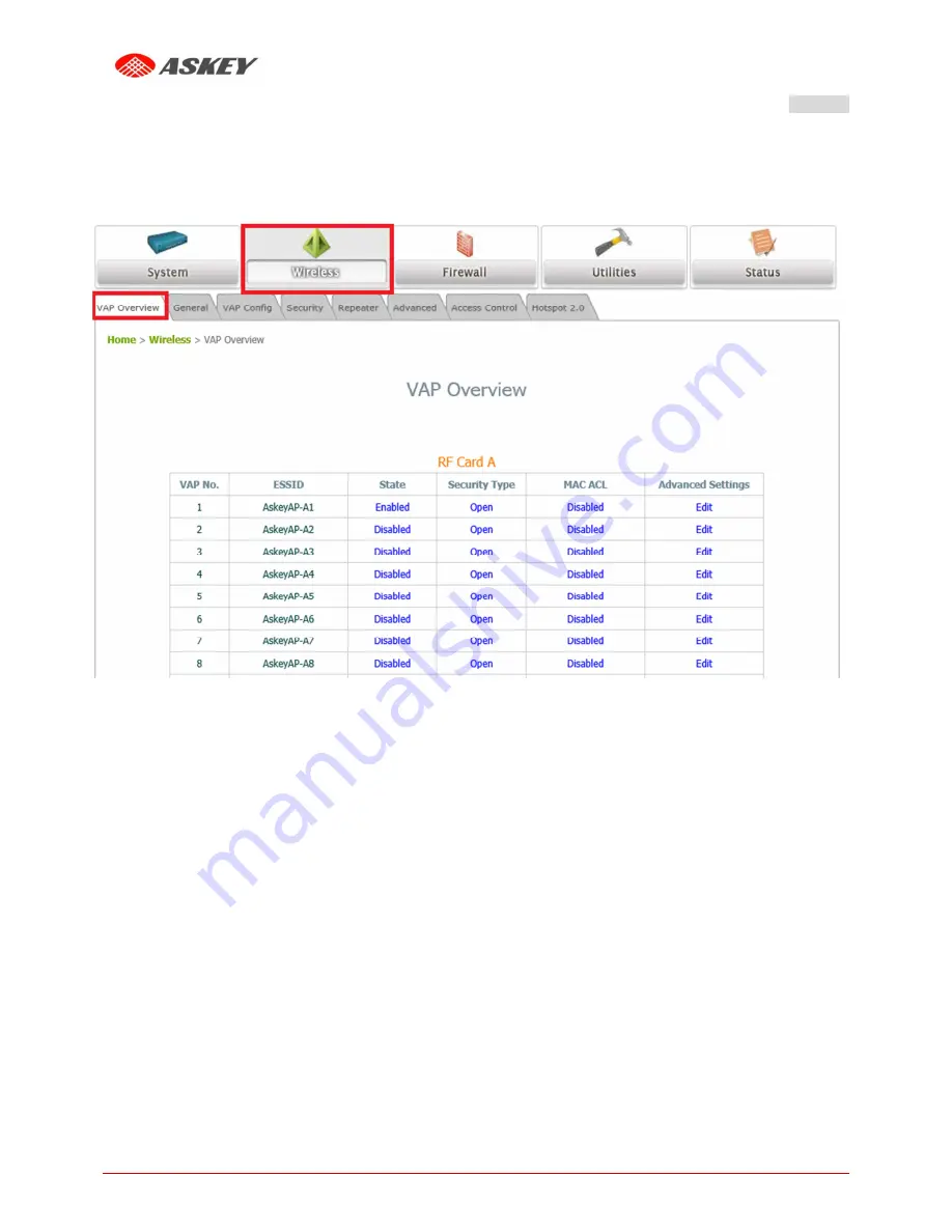
  Check VAP status

: 

After finishing VAP configuration, the status of enabled Virtual APs shall be reflected on the VAP 

Overview page. 

Virtual AP Overview Page


Summary of Contents for EAI2001S

Page 1: ...Quick Installation Guide EAI2001S Enterprise Access Point ...

Page 2: ...t is the property of Askey INC You may not copy reproduce distribute publish display perform or modify any part of this publication in any form or by any means without prior written permission from Askey INC You may not alter or remove any copyright or other notice from copies of the content All other brand and product names are claimed or registered marks of their respective companies ororganizat...

Page 3: ...nto an outlet on a circuit different from that to which the receiver is connected Consult the dealer or an experienced radio TV technician for help Any changes or modifications not expressly approved by the party responsible for compliance could void the user s authority to operate this equipment This device complies with Part 15 of the FCC Rules Operation is subject to the following two condition...

Page 4: ...ion is only valid for configurations combinations of software firmware and hardware provided and supported by Askey Inc The use of software or firmware not provided and supported by Askey Inc may result in the equipment no longer being compliant with the regulatoryrequirements European standards dictate maximum radiated transmit power of 100mW EIRP and frequency range 2 400 2 4835 GHz This equipme...

Page 5: ...PA and WPA2 The EAI2001S supports multiple point to point wireless links to form wider wireless network coverage EAI2001S also features multiple ESSIDs with VLAN tags and multiple Virtual APs great for enterprise applications such as separating traffic from different departments using different ESSIDs The PoE Uplink port is able to receive power from Power over Ethernet PoE sourcing devices This Q...

Page 6: ... status 3 2 4G_LED An LED indicator to show the 2 4G status 4 5G_LED An LED indicator to show the 5G status 5 Reset Press once to restart the system to reset the system to factory default settings hold for more than 5 seconds 6 USB The USB port for development engineers access 7 Console Console port for debugging 8 LAN Uplink PoE Port Offers uplink connection This port can be used to connect to a ...

Page 7: ...1 Place the EAI2001S at the best location The best location for EAI2001S is usually at the center of your intended wireless network Bracket assembly installation Step1 1 Place Mount in Bracket 2 Mount Bracket with Screw Nut Step2 1 First drill two holes in the wall or ceiling and then screw on the wall or ceiling The distance between the two screws is 150mm Noted Two screws must be purchased by th...

Page 8: ...t 2 Device clockwise rotation of the fixing tenon Device disassemble Step1 Press Bracket as shown in the figure to remove the latch Step2 Device counter clockwise to remove 2 Connect the EAI2001S to your network device Connect one end of the Ethernet cable to the Uplink port of EAI2001S and the other end of the cable to a switch a router or a hub EAI2001S is then connected to your existing wired L...

Page 9: ...ower socket EAI2001S Uplink port is capable of receiving DC currents Connect an IEEE 802 3at compliant PSE device e g a PoE switch to the Uplink port of EAI2001S with the Ethernet cable Now the Hardware Installation is complete Using a different power adapter may damage this system To verify the wired connection between EAI2001S and you switch router hub please also check the LED status indicator ...

Page 10: ...68 1 1 Subnet Mask 255 255 255 0 Steps 1 To access the Web Management Interface connect the administrator PC to the Uplink port of EAI2001S via an Ethernet cable Then set a static IP address on the same subnet mask as EAI2001S in TCP IP of your PC such as the following example IP Address 192 168 1 100 Subnet Mask 255 255 255 0 2 Launch the web browser on your PC by entering the IP address of EAI20...

Page 11: ...rprise Access Point ENGLISH 4 After a successful login to EAI2001S a System Overview page of the Web Management Interface will appear as depicted below The Web Management Interface System Overview Page 5 To logout simply click on the Logout button at the upper right hand corner of the interface to return to the Administrator Login Page Click OK to logout ...

Page 12: ...uide EAI2001S Enterprise Access Point ENGLISH Step 1 Change Administrator s Password Change Password Page Click on the Utilities icon on the main menu and select the Change Password tab Enter a new password with a length of up to 32 characters and retype it in the Re enter New Password field Click SAVE to save the changes Common Settings ...

Page 13: ...ettings Wireless General Settings Page Click on the Wireless icon on the main menu and then select the General tab Determine the Band Protocol and Channel settings Select your preferred Band Protocol and Channel for you wireless connection For example select 2 4GHz for the band 802 11g 802 11n for the protocol and 6 for the channel Noted The wireless country code is preset for the system software ...

Page 14: ...int ENGLISH Step 3 Configure VAP Virtual Access Point Profile Settings VAP Configuration Page VAP 1 shown EAI2001S supports up to 16 virtual APs VAPs per RF Card Configure VAP profile settings a Select the VAP Configuration tab to configure the settings of the desired VAP b Enable a specific VAP from the drop down menu of Profile Name and configure related settings below ...

Page 15: ...Quick Installation Guide Quick Installation Guide Quick Installation Guide EAI2001S Enterprise Access Point ENGLISH Check VAP status After finishing VAP configuration the status of enabled Virtual APs shall be reflected on the VAP Overview page Virtual AP Overview Page ...

Page 16: ...ck on the Wireless button on the main menu Select the Repeater Settings tab Choose WDS as the Repeater Type Choose the desired WDS profile a Enable WDS b Enter the Remote AP MAC Address peer AP and then Click SAVE If you are using another EAI2001S as the peer AP simply repeat the above mentioned steps to configure another peer AP s Note On each and every configuration page you may click SAVE to sa...

Page 17: ...d and configured successfully After EAI2001S s network configuration is completed please remember to change the IP Address of your PC Connection Properties back to its original settings in order to ensure that your PC functions properly in its real network environments It is strongly recommended to make a backup copy of your configuration settings For further configuration and backup information p...

Reviews: