ASI MFC2000 Operation Download Page 3

2022/03/16 04:45

3/18

MS2000, MFC2000 and RM2000 OPERATION

Applied Scientific Instrumentation - https://asiimaging.com/docs/
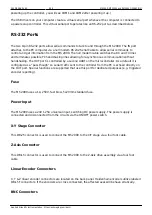
4 line version

2 line version

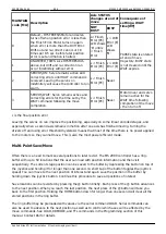
The status line at the bottom of the display indicates the command set (H high or L low), the XY
encoder mode (R rotary or L linear), and the Z encoder mode (R rotary or L linear). The next two
numbers show the next position to move to for ring buffer, and the number of positions stored,
respectively, separated by a colon (:). Controllers with the Auto-Focus option display the focus value
on this line as well. On the right side is a time clock. Some error codes are displayed in place of the
clock for a few seconds after they occur.

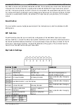
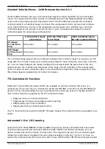
Mode 3 - SW 1 & 2 UP Dual Display with Status Line Shown

4 line version

2 line version

In this mode, two sets of number are shown for each axis. The number on the left is the current
position reported by the axis encoders. The number on the right is the target position that the
controller is trying to achieve.

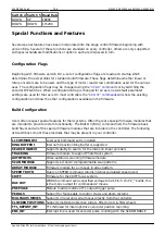
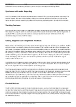
Mode 4 - SW 1 UP & 2 DOWN Dual Display with Firmware Version Line Shown

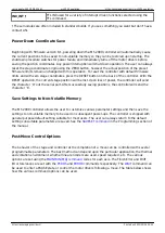
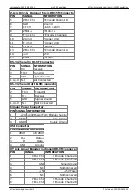
There are several status indicators that may appear on the right side of the axis line display (in
display columns 19 or 20). The meaning of these indicators is listed in the table below.

Table 1: Status Indicators in Order of Priority per Column

Summary of Contents for MFC2000

Page 1: ...ings for the joystick may be programmed and saved in rmware See the JSSPD command Command Encoder Knob The Command Encoder Knob is usually used to control the Z axis stage The relative speed of the kn...

Page 2: ...witch is not used or used for other special purposes LCD Screen Note MS2000 and RM2000 have a 4 line LCD MFC2000 controllers only have a two line LCD The Liquid Crystal Display LCD screen shows the cu...

Page 3: ...ell On the right side is a time clock Some error codes are displayed in place of the clock for a few seconds after they occur Mode 3 SW 1 2 UP Dual Display with Status Line Shown 4 line version 2 line...

Page 4: ...til the axis reaches target to the accuracy speci ed by the PC error variable Should the stage drift further from the current target by more than the E drift error variable the motors will re engage a...

Page 5: ...port is controlled by a second UART on the microcontroller As a default it is con gured as a pass though so serial tra c sent to the controller from the PC is echoed directly on the OUT port Special f...

Page 6: ...ces Switches 1 2 select the LCD screen options Switches 4 and 5 set up the serial baud rate for the RS 232 and USB interfaces Switches 3 6 select between linear and rotary encoders for the XY and Z ax...

Page 7: ...ten there are special rmware modules that are included to provide custom functionality The BUILD X BU X command lists the rmware basic build avor and all of the special rmware modules that are include...

Page 8: ...the current stage position will be lost Upon loss of power the controller will send the character O out the serial port After successfully saving positions the controller will send the character K Sav...

Page 9: ...near encoded stages and especially when a second axis remains in motion after one axis has nished moving Turning the drivers o and using error threshold hysteresis means that most of the time there is...

Page 10: ...teger multiple of the slowest speed Be aware that at the very slowest speeds the condition and cleanliness of the stage and the calibration of the analog stage driver circuitry can have a dramatic e e...

Page 11: ...ontroller to detect an error condition The motors are immediately turned o and the o ending axis is disabled If this happens a D character is displayed as the status indicator on the LCD display The u...

Page 12: ...some examples of the con gurations settings that can be changed See the CCA command for details The con guration ags are usually only changed when the controller is rst set up for a particular set of...

Page 13: ...king memory and clears the data from the Saved Position nonvolatile memory locations to ready those storage locations for when power is again shut o If the controller is RESET without turning o the po...

Page 14: ...tems On systems with a PIEZO axis this is the controled voltage when a commanded move to the PIEZO usually Z axis is made DAC_OUT with WRDAC command provides external analog output 6 TTL IN1 INPUT Aux...

Page 15: ...ted 9 N C Not Connected 10 X Lim U X Upper Limit 11 5V 5V X limits 12 Y Lim U Y Upper Limit 13 5V 5V Y limits 14 X Mot X Motor 15 5V 5V X encoder 16 X Enc Ch B X Encoder Channel B 17 Y Mot Y Motor 18...

Page 16: ...TION 2 R In Receive 3 T Out Transmit 5 GND Signal Ground 1 4 6 9 N C Not Connected RS 232 Serial Out DB 9M Connector PIN SIGNAL INFORMATION 2 T Out Transmit 3 R In Receive 5 GND Signal Ground 1 4 6 9...

Page 17: ...Connected IN BNC optional PIN SIGNAL INFORMATION Center TTL IN VIH 3 2V VIL 1 3V Outer GND Signal Ground OUT BNC optional TTL PIN SIGNAL INFORMATION Center TTL OUT VOH 4 4V VOL 0 1V IO Max 50mA Outer...

Page 18: ...0 10v 1 If you do not see Ports COM LPT when the drivers are installed and the controller connected and powered up then the computer may not fully support USB and RS 232 Certain inexpensive laptops ha...

Reviews: