Product Information Page
All specifications are subject to change without notice.
All sales subject to standard terms and conditions.
© 2017 Ashcroft Inc.
ashcroft.com
info@ ashcroft.com
1.800.328.8258
Rev. A 02/17, Page 6 of 8
Step
11
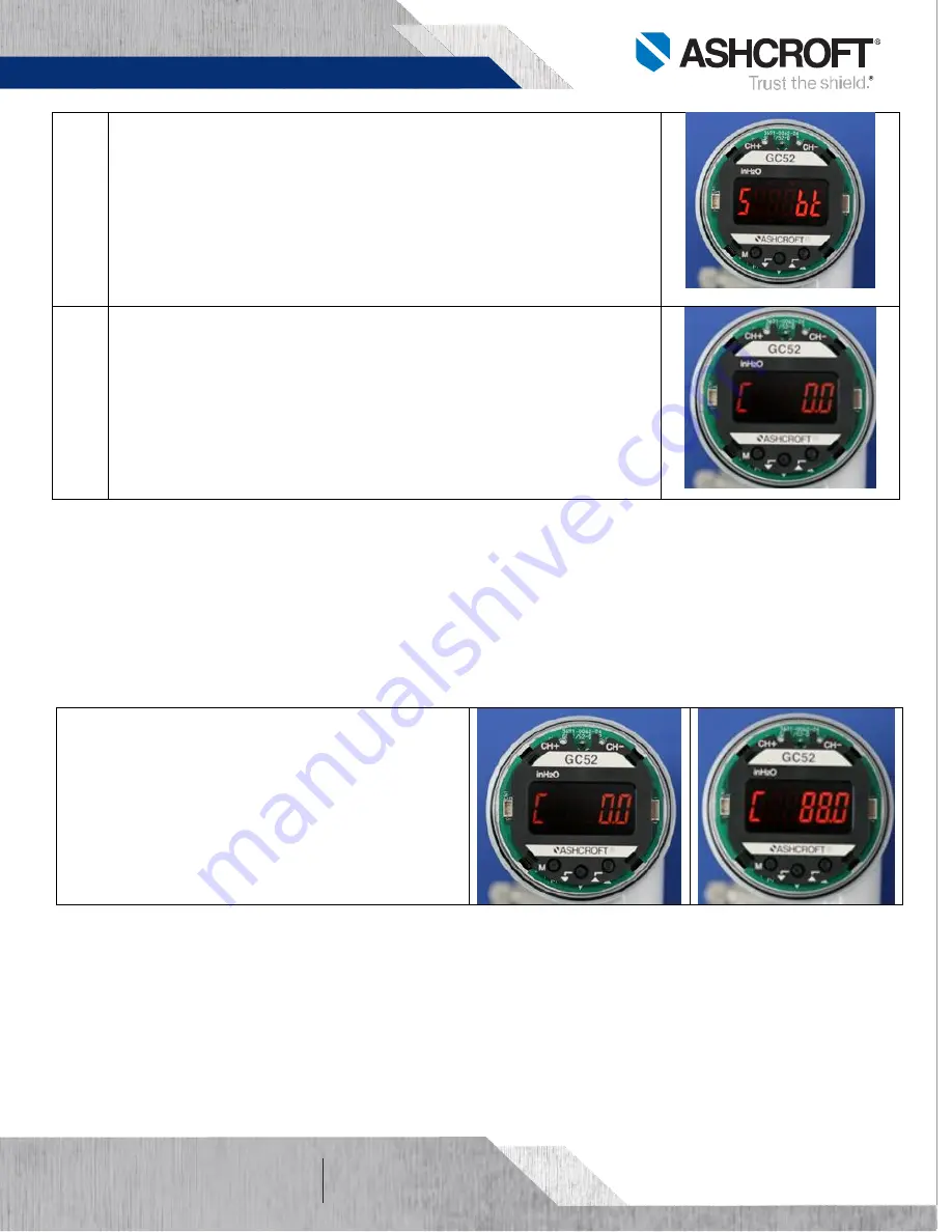
S bt
To enter switch mode of momentary flow rate and integrated
volume. There is manual mode (bt) or automatic mode (ti).
For this application manual switch mode shall be selected.
It only displays integrated volume when cover is removed and M
button is pressed. Otherwise it only displays flow rate.
Automatic setting time is selectable from 1 to 10 seconds cycle.
Press UP or Down arrow until “bt” is displayed.
Press and release M button to select and move to the next step.
Step
12
C 0.0
Loop check mode allows program and analog output
verification with the transmitter pressurized or non-pressurized. It
simulates the process and allows for troubleshooting.
Press Up or Down arrow to change within transmitter range (0 to 88
GPM of water).
Press and release M button to return to the begin of program
After verification press and hold M button for more three seconds to
return to measuring mode.
Function Verification:
The GC52
loop-check
allows to verify program and analog output with the transmitter pressurized or
non-pressurized.
Once Step-11 is reached, the unit is in Loop-
check mode. The system can be verified by
increasing or decreasing the flow rate value (0 to
88 GPM of water).
Use the Up or down arrow and observe the
display segments get brighter as the flow rate
value increases. That, is an indication that the
analog output and wiring are reacting properly.


