© 2020 ASCO Power Technologies. All Rights Reserved
For troubleshooting, call technical assistance at 1-800-237-4567 or [email protected]
14
IO-70075
08/2020
ASCO 450/451/452/453 Surge Protective Device (SPD)
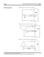
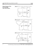
Wiring
The ASCO 450/451/452/453 either comes with terminal lugs, internal or
external rotary disconnect switch.
ASCO 450/451/452/453 SPD:
Follow steps 1 through 7 to make wiring connections to units with either
rotary disconnect switch or terminal block connection:
1.
Turn off all power supplying this equipment before working on or inside
any enclosure containing this equipment.
2.
Confirm SPD is rated for your system by comparing voltage
measurements to the Line Voltage (L-L, L-N) on the product label.
3. Identify proper location for surge protective device. Locate as close
as possible to the panel being addressed so the wires are as short as
possible. Mount unit securely.
Note: The surge protective device must be installed in an accessible
location as described in the NEC.
4. Install in accordance with national and local electrical codes
for overcurrent protection recommendations and wire ampacity
considerations.
Note: Use on solidly grounded systems unless the SPD model is
designed for installation on ungrounded/HRG systems.
Note: See “Terminals, Wire Size, and Installation Torque” and Table 2
on page 9 for acceptable wire size and installation torque.
5. Twist conductors 1/2 turn or more for every twelve inches of length. Do
not loop or coil wires. Be sure to maintain adequate wire bending space
per NEC.
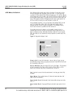
6. If the remote signaling contacts of the diagnostic display panel are to
be used, refer to the section, “Dry Contacts”, on page 21 for wiring
instructions.
UL Conditions of Acceptability
For use only in equipment where the acceptability of the combination is
determined by Underwriters Laboratories
®
. When installed in the end-use
equipment, the following are among the considerations to be made:
1. A suitable electrical enclosure shall be provided in the end-use product.
2.
The device is intended for factory and field installations with the suitability
of the connections (including spacing’s between factory connectors)
determined in the end-use application.
3. The Voltage Protection Rating (VPR) shall be determined in the end-
product where applicable.
4. The SPD unit has been subjected to the following tests of UL 1449,
4th Edition:
a. Surge Testing (VPR)
b. Nominal Discharge Current Test (20 kA)
c. Dielectric Voltage Withstand
d. Current Testing (200 kA Short Circuit Current, Intermediate Protective
Devices (OCPD) or external enclosures.
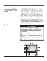
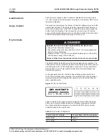
HAZARD OF ELECTRIC SHOCK, EXPLOSION, OR ARC FLASH
• On a high-leg delta installation, the high-leg of the power system must
be connected to the B phase lug of the SPD.
Failure to follow these instructions will result in death or serious injury.
DANGER


