ASC Gruvlok 3006 Manual Download Page 5

BUILDING CONNECTIONS THAT LAST

5

GROOVER DESCRIPTION

*“

RIDGID” is a registered trade mark of Emerson Electric Company.

Note: See Section XI for further details of parts for the 3006 and 3006C Roll Groover.

A.  3

006 STANDARD EQUIPMENT

Roll Groover complete with Adjustable Support Leg Assembly and 
roller sets for grooving 2"-6" and 8"-12" steel pipe, Steel/CTS Dual 
Guide Roll Assembly, hydraulic pump with pressure gauge, and two 
depth adjustment gauges. This unit is designed for direct attachment 
to your Ridgid

®

 300 Power Drive. Complete with comprehensive setup, 

operating and troubleshooting instructions.  
Shipped in a reusable wooden storage crate.         
 Approximate shipping weight: 225 pounds.  
Required Ridgid® 300 Power Drive not included.

B.  3006 OPTIONAL EQUIPMENT

CTS COPPER SYSTEM:


• 2"- 8" CTS Copper System Grooving Rolls, 2"- 4" CTS Depth 

Gauge, and 5"- 8" CTS Depth Gauge.

A.  3

006C STANDARD EQUIPMENT

Roll Groover complete with Adjustable Support Leg Assembly and 
CTS Copper System roller set for grooving 2"-6" copper tube, CTS 
Guide Roll Assembly, hydraulic pump with pressure gauge, and 2"-6" 
Universal Diameter Gauge. This unit is designed for direct attachment 
to your Ridgid

®

 300 Power Drive. Complete with comprehensive setup, 

operating and troubleshooting instructions. 
 Shipped in a reusable wooden storage crate.   
Approximate shipping weight: 215 pounds.  
Required Ridgid

®

 300 Power drive not included.

B.  3006C OPTIONAL EQUIPMENT

STEEL OPTION:


• Consisting of 2"-6" and 8"-12" roll sets, Steel/CTS Dual 

Guide Roll Assembly, and two depth adjustment gauges

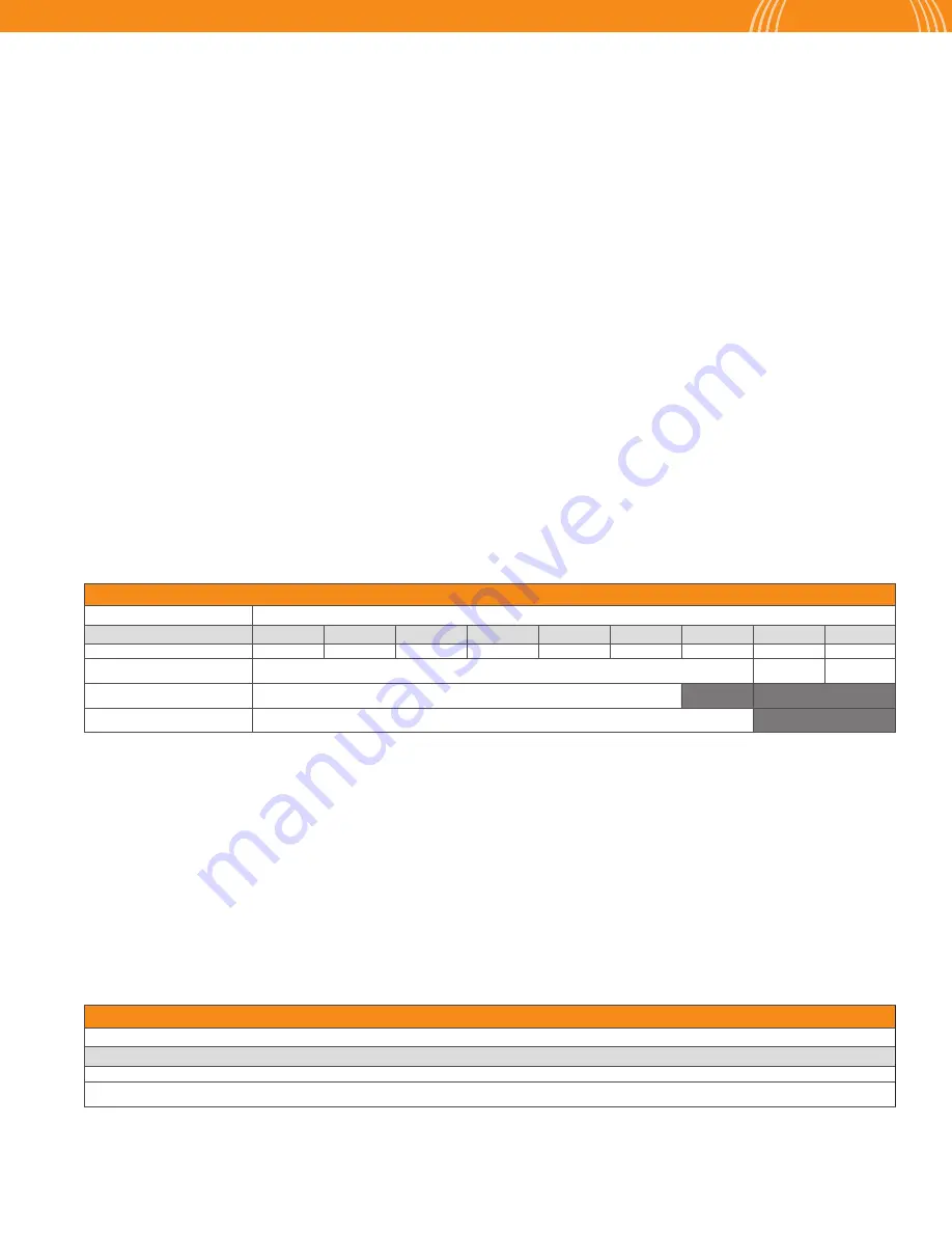
1.  All wall thicknesses shown are the maximum wall thicknesses for the indicated pipe material.
2.  Minimum wall thickness for each pipe material and size is: 

Steel: 2"-12" Schedule 10 

Stainless Steel:  2"- 12" Schedule 10S, 40S 

Copper: 

2"- 21/2" - Type M   


3"- 8" - Type DWV

3.  Please contact an Anvil Representative for information on grooving alternate materials and wall thickness.

GROOVER CAPABILITY

Pipe Material

Pipe Size/Wall Thickness (Schedule)

1,2

In.

2

1

2

3

4

5

6

8

10

12

DN(mm)

50

65

80

100

125

250

200

250

300

Steel

Schedule 10, 40

0.188

"

0.219

"

Stainless Steel

Schedule 10S, 40S

Copper

K, L, M & DWV

MODEL 3006/3006C STEEL PIPE GROOVING TIMES (MINUTES: SECONDS)

Pipe Size (In./DN(mm))/Max Steel Pipe Wall Thickness

2

2

1

2

3

4

5

6

8

10

12

50

65

80

100

125

150

200

250

300

0:20

0:20

0:25

0:30

1:00

1:20

1:35

1:50

2:20

C. 3006/

3006C GROOVER CAPABILITY

D. GROOVING TIMES

 This chart shows approximate grooving times with the groover set-up for the proper size and groove diameter and the pipe properly positioned on the 
groover.  The times shown are average times from the start of rotation of the pipe in the grooving rolls to completed groove.

Summary of Contents for Gruvlok 3006

Page 1: ...Gruvlok Roll Groover 3006 3006C Manual ...

Page 2: ...ings steel pipe nipples and couplings pipe hangers and supports channel and strut fittings mining and oil field fittings along with much more As an additional benefit to our customers Anvil offers a complete and comprehensive Design Services Analysis for mechanical equipment rooms to help you determine the most effective and cost efficient piping solutions for your pipe system At Anvil we believe ...

Page 3: ...TEEL PIPE 09 GROOVING CTS COPPER SYSTEM 10 GROOVING ROLL CHANGE 11 GROOVER MAINTENANCE 13 REPLACEMENT PARTS 14 GROOVE SPECIFICATIONS 15 TROUBLESHOOTING 17 Carefullyreadandunderstandinstructionsbeforeassembling andoperatingtheGroover s Becomethoroughlyfamiliar withtheGrooveroperation usageandpossiblehazards specifictotheGroover s IMPORTANT SAFETY NOTICE ...

Page 4: ...EL 3006 3006C ROLL GROOVERS ARE TO BE USED ONLY FOR ROLL GROOVING OF PIPE These operating instructions pro vide important information for the safe operation of the Groover to protect the operator from possible serious injury The Groover is designed for safe reliable operation However unforeseen circumstances impossible to predict could result in an accident Following the information in these opera...

Page 5: ...d troubleshooting instructions Shipped in a reusable wooden storage crate Approximate shipping weight 215 pounds Required Ridgid 300 Power drive not included B 3006C OPTIONAL EQUIPMENT STEEL OPTION Consisting of 2 6 and 8 12 roll sets Steel CTS Dual Guide Roll Assembly and two depth adjustment gauges 1 All wall thicknesses shown are the maximum wall thicknesses for the indicated pipe material 2 Mi...

Page 6: ...in Section IV Back of tool should sit over flat plate with sockets underneath Use the Adjustable Support Leg Assembly for the 3006 3006C Roll Groover whenever long pieces of pipe tubing or heavier wall thicknesses are being grooved The gruvlok model 3006 3006c roll groovers are designed for use with a ridgid 300 power drive 1 4 2 5 3 6 Extend the mounting arms of the Ridgid 300 power drive approxi...

Page 7: ...ase location for both the Groover and power drive Use one 1 roller pipe stand to support the pipe Adjust the outboard pipe stand to assure proper contact with the guide rolls Pipe stand should be 65 75 of the pipe length away from Groover Looking at the front of the Groover the pipe stand should be positioned to angle the tube approximately 0 to 1 4 downward away from the front of the Groover and ...

Page 8: ... size ranges Place the correct pipe size area for the size of pipe being grooved under the lower hex nut groove diameter stop Increase the pump pressure so that the pipe is firmly held between the groove and drive rollers without forming a dent Turn the lowest hex nut groove diameter stop to snug against the top surface of the Groover 2 1 2 1 3 3 Set up and position the pipe as shown on page 7 Mai...

Page 9: ...th the pipe OD Check to see that the Ridgid 300 drive directional switch is set to reverse clockwise rotation of the pipe looking at the front of the Groover start the drive motor by depressing the foot switch to rotate the pipe Assure that the pipe is tracking firmly against the back of the bottom roll With the pipe rotating increase grooving force by slowly pumping the hydraulic pump handle to r...

Page 10: ...ssures Open the hydraulic hand pump release valve by turning counterclockwise Remove the tube from the Groover Using a pi tape check the groove diameter produced and compareittospecifications presented on page 17 1 4 2 5 6 3 HEX NUT ADJUSTMENT GROOVE DIAMETER CHANGE Turns Inches 1 6 024 1 3 048 1 2 071 2 3 095 5 6 119 1 142 Clockwise rotation Increase groove diameter Counterclockwise rotation Decr...

Page 11: ...the back bearing revealing the dowel pin hole in the shaft Push the dowel pin completely out of the shaft 3 8 pin driver Pull the bottom roller out from the front of the Groover 1 3 1 2 2 3 C BOTTOM DRIVE ROLL A GUIDE ROLL MOUNTING PLATE GROOVING ROLL CHANGE ROLL REMOVAL Note First remove the guide roll mounting plate then the top groove roll and last the bottom drive roll NOTE Loosen approximatel...

Page 12: ...o the hole in the mounting block at the front of the groover head Slide the shaft up to expose the threaded portion at the top of mounting block Using a 3 4 wrench install and snug the hex nut on the top of the adjustment shaft 1 2 3 1 3 4 2 3 C BOTTOM DRIVE ROLL A GUIDE ROLL MOUNTING PLATE GROOVING ROLL CHANGE ROLL INSTALLATON Raise the groove roll between the front and back plates of the groover...

Page 13: ...ease to left key with a grease gun with a 1 4 fitting attachment to the upper grease fitting on the left side of the Groover Apply grease to right key with a grease gun with a 1 4 fitting attachment to the right side of the Groover 1 2 C HYDRAULIC MAINTENANCE A GREASE FITTINGS B REPLACEMENT PARTS GROOVING MAINTENANCE 13 Routine maintenance of the model 3006 3006C Roll Groover requires periodic app...

Page 14: ... L 1 2 GL11230 ID PART NAME PART NO 3 Hex Bolt 5 8 11 L 1 5 GL11091 4 Cap Screw 1 4 20 L 1 2 GL11230 5 Safety Mesh GL11280 6 Hydraulic Ram GL11095 7 Jam Nut 7 8 14 GL11277 8 Hex Nut 7 8 14 GL11276 9 Top Roller 2 6 Steel Top Roller GL11285 8 12 Steel Top Roller GL11300 2 8 CTS Copper Top Roller OPT GL13803 10 Cup Point Set Screw 5 18 GL11289 11 Dowel Pin GL11290 12Cone Pt Set Screw 5 18 GL11066 ID ...

Page 15: ...0 625 0 344 2 720 0 018 0 078 0 083 2 980 65 73 0 0 74 0 74 15 88 8 74 69 09 0 46 1 98 2 1 75 7 3 3 500 0 035 0 031 0 625 0 344 3 344 0 018 0 078 0 083 3 600 80 88 9 0 89 0 79 15 88 8 74 84 94 0 46 1 98 2 1 91 4 31 2 4 000 0 040 0 031 0 625 0 344 3 834 0 020 0 083 0 083 4 100 90 101 6 1 02 0 79 15 88 8 74 97 38 0 51 2 11 2 1 104 1 4 4 500 0 045 0 031 0 625 0 344 4 334 0 020 0 083 0 083 4 600 100 1...

Page 16: ...ONS 1 2 3 4 5 6 7 8 Nominal Size Tubing Outside Diameter Gasket Seat A 0 03 in 0 76mm Groove Width B 0 03 0 00 in 0 76 0 00mm Groove Diameter C Nominal Groove Depth D Min Wall T Max Flare Diam Actual Tolerance Actual Tolerance 0 000 In In mm In mm In mm In mm In mm In mm In mm In mm In mm In mm 2 2 125 0 002 0 002 0 610 0 300 2 029 0 020 0 048 0 058 2 220 54 0 0 05 0 05 15 5 7 6 51 54 0 51 1 2 1 6...

Page 17: ...top to correct IPS VerifyGrooveDiameterStopNutsare fullybackedoff 3 Pipe flare excessive Pipe stand adjusted too high Tool is tilted forward Incorrect pipe stand offset positioning Pipe is over tracking Warped bottom roll shaft See PipeSet up Positioning See GrooverSet up See PipeSet up Positioning Replacedamagedbottomrollshaft Thehingedcollarmaybemissing Replacedamagedparts 4 While grooving loud ...

Page 18: ...l industrial fire protection oil and gas and commercial and residential construction Its portfolio of leading brands includes ABZ Valve AFCON Anvil Anvil EPS Anvil Services Basic PSA Beck Catawissa Cooplet FlexHead FPPI Gruvlok J B Smith Merit North Alabama Pipe Quadrant SCI Sharpe SlideLOK SPF and SprinkFLEX With headquarters in Commerce CA and Exeter NH ASC also has ISO 9001 2015 certified produ...

Reviews: