


10
Aruba 518 Series Ruggedized Access Point
| Installation Guide
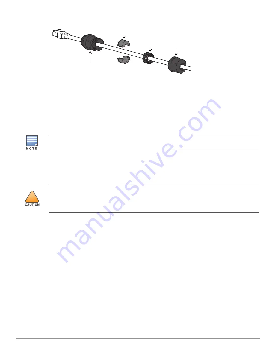
Figure 7
Installing the Ethernet Cable Gland
1. Remove the dust cap from the Ethernet port
2. Slide the sealing nut, clip, split grommet and gland body over the cable.
3. Insert the RJ45 connector to the Ethernet port.
4. Screw the gland body onto the Ethernet port.
5. Combine the two split parts of the grommet over the cable, and move it towards the gland body until it
locates at the recess of the gland body.
6. Move the clip towards the gland body, passing over the grommet, until the wavy end of the clip properly fits
into the wavy end of the gland body.
7. Screw the sealing nut onto the gland body
Software
For instructions on choosing operating modes and initial software configuration, refer to the AP Software Quick
Start Guide.
Verifying Post-Installation Connectivity
The integrated LEDs on the access point can be used to verify that the access point is receiving power and
initializing successfully (see
and
). Refer to the
AP Software Quick Start Guide
for further details
on verifying post-installation network connectivity.
Electrical and Environmental Specifications
Electrical
Ethernet
E0: 100/1000/2500Base-T auto-sensing Ethernet RJ-45 Interfaces
E1: 100/1000Base-T auto-sensing Ethernet RJ-45 Interfaces
Power over Ethernet (IEEE 802.3at and 802.3bt compliant)
Environmental
Operating
Temperature: -40ºC to 55ºC (-40ºF to 140ºF)
Sealing Nut
Clip
Gland Body
Split Grommet
Two grommets are provided in the package for use with the Ethernet cables. One is applicable for cables with
4-6 mm diameter, and another is applicable for cables with 6-10 mm diameter.
!
Aruba access points are classified as radio transmission devices, and are subject to government regulations of
the host country. The network administrator(s) is/are responsible for ensuring that configuration and operation
of this equipment is in compliance with their country’s regulations. For a complete list of approved channels in
your country, refer to the
Aruba Downloadable Regulatory Table
at
https://www.arubanetworks.com/techdocs/DRT/Default.htm
.


