ARTRAY ARTCAM-130SWIR-CL Setting Manual Download Page 5


© 2004 – 2018 ARTRAY Co., Ltd   

130SWIR-CL


Camera Link


Setting Manual


5


Rev.1.04


5. 

Communication Specifications 

5.1. 

About the settings of the product. 

To change or check the settings of the Camera Link camera, you can send command to the camera 
through a serial communication software. 

5.2. 

Communication Method 

The serial communication method is as follows:   

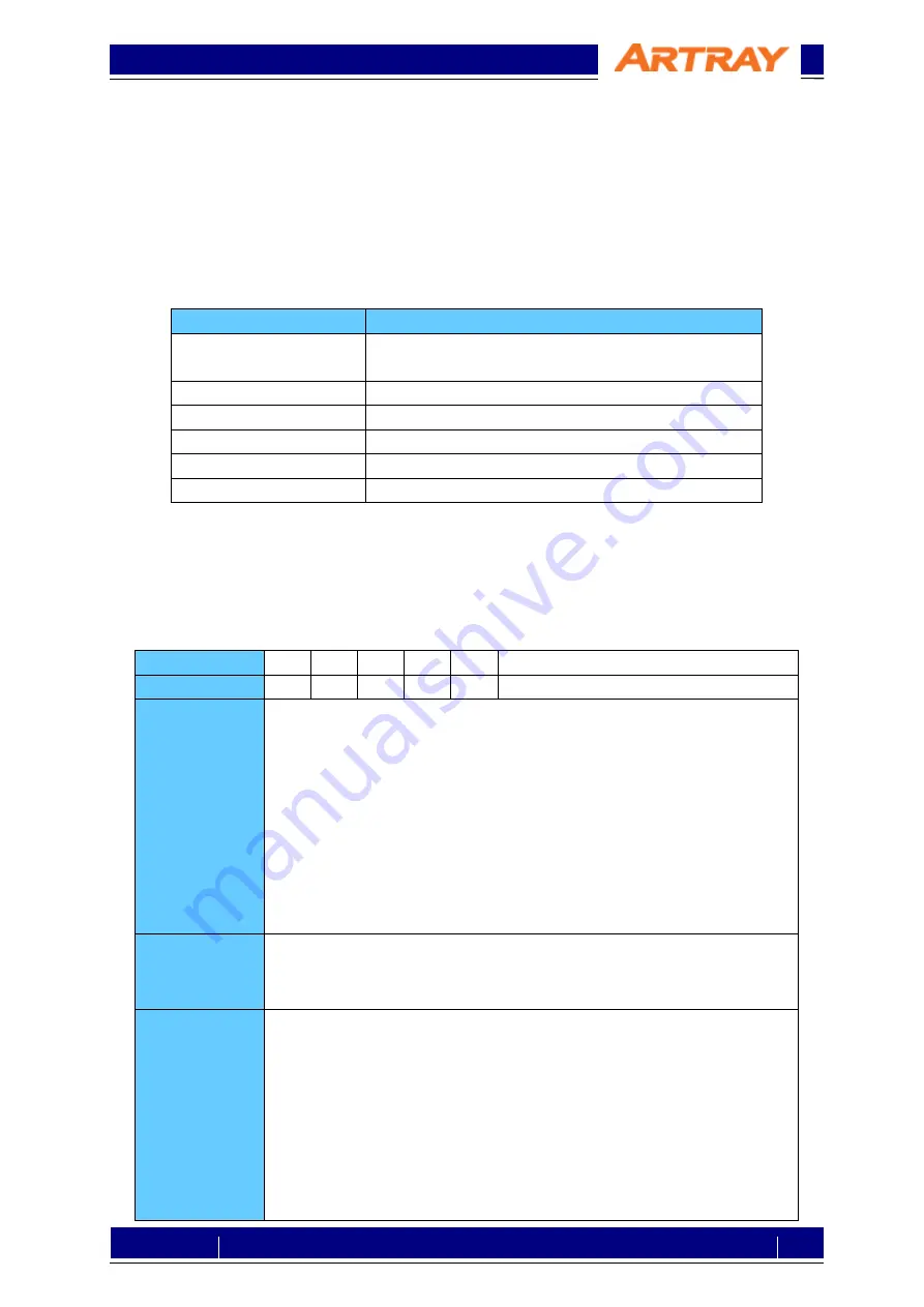
Table 5-1: Communication Method 

Item 

Contents 

Communication Form 

Asynchronous serial communication 
(In accordance with standards of RS232C) 

Baud Rate 

9600bps 

Data 

8 bit 

Parity 

None 

Stop 

1 bit 

Flow Control 

None 


5.3. 

Command Format 

Please give command to the camera through serial communication software with the format listed 
below. If the format is not correct, the camera could not be controlled. 
Please be sure to use half-width characters of ASCII code. 

Table 5-2: Command Format 


Format 

cmd 


-opt 


val 

CR or LF or CR+LF


Details 

1: One letter which represents the main purpose of the command.   
2: One space (blank) as delimiter. (Omissible) 
3: Option correspondent with the main purpose.   

The format is a letter going after a “-”. 

4: One space (blank) as delimiter. (Omissible) 
5: Value setting: enter the value if necessary. 

Decimal numerical value: enter the number directly. 
Hexadecimal numerical value: enter the number after an “x.” 
The default value would be 0 if there is no value entered. 

6: Line feed code 

Response 

Normal: OK

(CR+LF) 

  If response is a value: 

"value"

(CR+LF) 

Abnormal: NG

(CR+LF) 

Note 

The command will be distinguished once the  line feed code is sent out. If 
any none-

half-width characters are typed (e.g. BackSpace) before line 

feed code, the response must be NG. (If only line feed code is typed, 
there will be no reaction.)


If you want to cancel the command, type a none-

half-width character before 

line feed code, the response will be NG.


It doesn’t matter the letters of command is in upper case or lower case. 
Option  is  omissible.  (In  this  case,  a  default  option  will  be  chosen 
automatically.) 


Summary of Contents for ARTCAM-130SWIR-CL

Page 1: ...2004 2018 ARTRAY Co Ltd 130SWIR CL Camera Link Setting Manual 1 Rev 1 04 ARTCAM 130SWIR CL Camera Link Setting Manual rev 1 05...

Page 2: ...Format 5 5 4 List of Commands 6 5 5 Commands Details 7 5 5 1 Reset 7 5 5 2 Shutter 8 5 5 3 External I O 9 5 5 4 Analog Gain 11 5 5 5 Digital Gain 12 5 5 6 Offset 13 5 5 7 Black Level Correction 14 5...

Page 3: ...nts Item Note Camera Link Frame Grabber Board Compatible with Base Configuration Viewer Software Software accompanying with grabber board or ArtMeasure Serial Communication Software e g Tera Term PC A...

Page 4: ...ified Grey Level 85 000MHz 3 2 Resolution The following table shows the maximum pixels of this camera Table 3 2 Resolution Model Horizontal Pixels Vertical Pixels ARTCAM 130SWIR CL 1280 1024 4 Connect...

Page 5: ...or LF or CR LF Details 1 One letter which represents the main purpose of the command 2 One space blank as delimiter Omissible 3 Option correspondent with the main purpose The format is a letter going...

Page 6: ...gger polarity settings a O Select signal of external output 1 b O Select signal of external output 2 Analog Gain a l Low gain Option is omissible m Medium gain Digital Gain g y ON n OFF v O Settings O...

Page 7: ...ssible 4 Line feed code Response Normal OK Abnormal NG Note To start camera While camera is already turned on plug in adapter and start again Table 5 5 Stop Camera 1 2 3 4 Format x p Details 1 x Reset...

Page 8: ...s Mode 1 2 3 4 Format i r Details 1 i Shutter 2 Delimiter Omissible 3 r Option asynchronous mode 4 Line feed code Response Normal OK Abnormal NG Note To change to asynchronous mode Table 5 9 Shutter S...

Page 9: ...al OK Abnormal NG Note To change external trigger to one of followings 0 external I O 1 CC1 2 CC2 3 CC3 4 CC4 Table 5 11 External trigger polarity settings 1 2 3 4 5 6 Format p p val Details 1 p Exter...

Page 10: ...normal NG Note To change external output 1 to one of followings 0 Low fixed 1 LINE_VALID 2 FRAME_VALID 3 TRIG_READY 4 STROBE 8 High fixed Table 5 13 Select signal of external output 2 1 2 3 4 5 6 Form...

Page 11: ...tails 1 p Analog gain 2 Delimiter Omissible 3 l Option low gain Omissible 4 Line feed code Response Normal OK Abnormal NG Note To set analog gain low Table 5 15 Medium Gain 1 2 3 4 Format a m Details...

Page 12: ...able 5 17 Digital Gain OFF 1 2 3 4 Format g n Details 1 g Digital gain 2 Delimiter Omissible 3 n Option digital gain OFF 4 Line feed code Response Normal OK Abnormal NG Note To disable digital gain Ta...

Page 13: ...ble offset Table 5 20 Offset OFF 1 2 3 4 Format o n Details 1 o Offset 2 Delimiter Omissible 3 n Option offset OFF 4 Line feed code Response Normal OK Abnormal NG Note To disable offset Table 5 21 Off...

Page 14: ...level correction Table 5 23 Black Level Correction OFF 1 2 3 4 Format l n Details 1 l Black level correction 2 Delimiter Omissible 3 n Option black level correction OFF 4 Line feed code Response Norm...

Page 15: ...xel Correction Table 5 26 Defective Pixel Correction ON 1 2 3 4 Format f y Details 1 f Defective pixel correction 2 Delimiter Omissible 3 y Option defective pixel correction NO Omissible 4 Line feed c...

Page 16: ...emperature as 25 C enter 25 Please enter whole number between 10 to 40 only or the response will be NG Table 5 29 Temperature Readout 1 2 3 4 Format t r Details 1 t Temperature control 2 Delimiter Omi...

Page 17: ...frame transfer 5 5 12 Camera Mode Table 5 32 SIM Mode 1 2 3 4 Format z s Details 1 z Camera mode 2 Delimiter Omissible 3 s Option SIM mode Omissible 4 Line feed code Response Normal OK Abnormal NG Not...

Page 18: ...elimiter Omissible 3 c Option camera name Omissible 4 Line feed code Response Normal ARTCAM 130SWIR CL example Abnormal NG Note To show camera name Table 5 35 Firmware Version 1 2 3 4 Format n v Detai...

Page 19: ...board is recognized normally If you use our recommendations listed in table 2 2 the device names should be recognized as follows Table 6 1 Devices Recognized No Device 1 PIXCI EB1 PCI Express Camera...

Page 20: ...pter to the camera Figure 6 2 Icon of Tera Term After starting the software please choose the port correspondent with the name shown in device manager At the time this manual is made it is shown as CO...

Page 21: ...er operation but not necessary to be Table 6 2 Communication Protocol Item Settings New line Receive CR New line Transmit CR LF Local echo Check the box Figure 6 5 To Set up Terminal on Tera Term Afte...

Page 22: ...the software you will see welcome message and license information If you have already registered please click OK directly If a warning or precaution concerning the license shows up you may not complet...

Page 23: ...y area First please set communication settings choose Configure to set Camera Link configuration bit tap and color Please refer to table 3 1 to confirm the Camera Link format Figure 6 10 Configure Set...

Page 24: ...Camera Link in Timing Please refer to table 3 1 to confirm the Camera Link format Figure 6 12 Timing Settings The settings are finished now The image will be displayed either by clicking Live in Capt...

Reviews: