Page 5
Rail-Switch II User Guide
Configuration
Rail-Switch II uses one channel to control
each relay, requiring 6 channels in total.
There are various configuration options
(including start address programming). These
are accessed using RDM, which requires a
suitable programming interface.
One option is Commissioner rdmx, a handheld
RDM programming tool available from Artistic
Licence.
Alternatively, Rail-Switch II can be connected
to an Art-Net network using an interface
product such as Art-Lynx O/P or Net-Lynx
O/P. Configuration is then achieved using
DMX-Workshop, a PC software application
for managing Art-Net networks (available as
a free-of-charge download from the Artistic
Licence website, www.artisticlicence.com).
Rail-Switch II has front-panel LED indicators
for the following functions:
Data (upper):
OFF = no data received
Green = DMX and RDM received
Yellow = DMX only received
Alternating green/yellow = Rail-Switch II is
in preset playback mode or test mode (see
‘Configuration’ below)
Power/Locate (lower):
Green = Power
Flashing green = RDM locate is active
An RDM locate sent to the root or the sub-
devices will have the identical effect of causing
the power indicator to flash.
Relays 1 - 6 (right-hand side):
Blue = Relay is energised
This windows-based application provides a
convenient means of accessing the Rail-Switch
II configuration menus. DMX-Workshop can
also be used for product firmware uploads.
Preset mode
It is possible to pre-programme Rail-Switch
II such that it can be installed without a DMX
controller. Rail-Switch II has 8 preset memories
which can be used to record different on/off
combinations of the six relay outputs.
DMX-Workshop allows these settings to be
captured and played back. To access the
relevant menus, right-click on the Rail-Switch
II RDM device (as shown above). Please note
that the data captured is always the DMX512
input, independent of the currently selected
output.
LED Indication
Start address programming
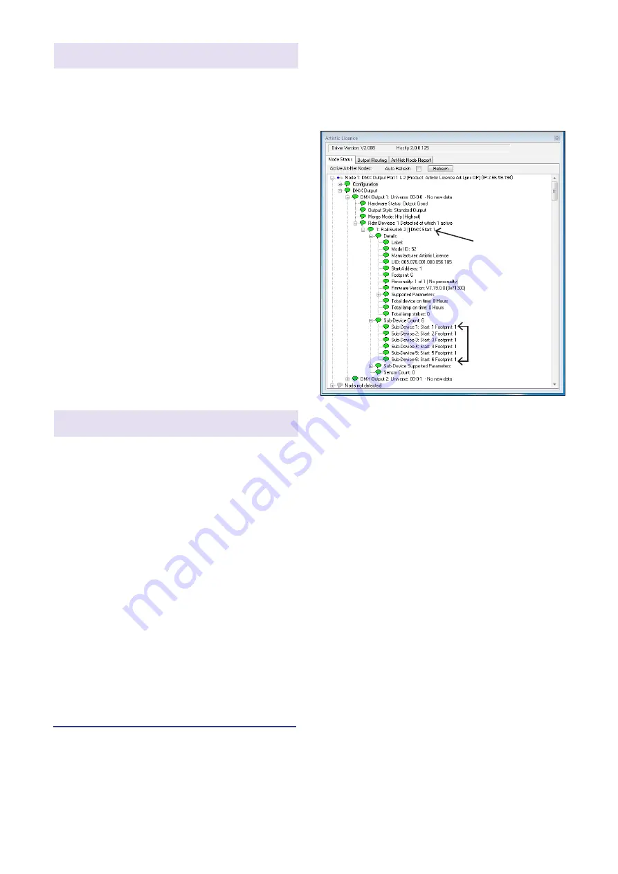
In the DMX-Workshop ‘Node List’ screen,
Rail-Switch II appears as an RDM device,
with each relay listed as a sub-device (see
screenshot below).
DMX-Workshop
If the user wishes all 6 output channels to be
consecutively addressed, this is achieved by
setting the RDM device start address (right-
click on the RDM device entry). Alternatively, if
the user wishes to individually set the address
of each channel, this is achieved by setting
the start address of each sub-device (right-
click on the desired RDM sub-device).
Generally, right-clicking on any entry brings
up a menu of the available options.
RDM device
RDM
sub-device


