


25
20-740/745
RF MULTIPLEXER MODULE
pickering
Section 5
Self Test
5.1 Self-Test Function
Self-Test is invoked at power on and may also be operated under software (*TST?) or via a recessed push button. Self-
Test pass is indicated on a front panel LED with a full pass/fail description available using the DIAGNOSTIC? command.
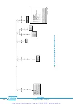
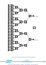
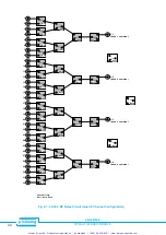
Self-Test comprises 2 levels, see Fig 5.1:-
1.
Logic Test: Checks all logic including on-board microprocessor, relay drivers etc.
2.
Relay Coil Test: All reed relay coils are checked for continuity.
Note: A spare relay is mounted onto the relay circuit board for fast repair, additional relays are available from Pickering
Interfaces.
5.2 Self-Test Operation
If self test is run under software control it will firstly clear the whole multiplexer (Manual Test will only function when the
module is in a clear state).
When the selftest has finished the multiplexer will be returned to an all clear state (i.e. the previous state will not be
remembered!).
5.3 Detailed Self Test Reporting using the DIAGNOSTIC? Query
The DIAGNOSTIC? query will give an ASCII string detailing any self test failures. These will include:-
Logic:
µ
P, RAM, EPROM, Relay Drivers, Invalid Link Settings etc.
Relay Coils:
Open Circuit Coil.
This string is not intended to be processed by the user’s software, it is suitable for copying directly onto the screen of your
control computer. This information will then indicate maintenance required (please contact Pickering for further help).
SELF TEST INITIATED BY:
• POWER ON
• *TST? QUERY
• MANUAL BUTTON
LOGIC TEST:
•
µ
P BOARD
• RELAY BOARD
RELAY COIL TEST
COIL
TEST FAIL
YES
NO
YES
NO
SELF TEST FAIL:
• ERROR LED ON
• USE DIAGNOSTIC?
COMMAND TO GET
ERROR MESSAGE
SELF TEST PASS
LOGIC
TEST FAIL
CLEAR MODULE
Fig 5.1 Self-Test: Basic Flow
Diagram
Artisan Scientific - Quality Instrumentation ... Guaranteed | (888) 88-SOURCE | www.artisan-scientific.com