background image

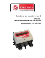
Installation and operation manual

DPC200 - 

DIFFERENTIAL PRESSURE CONTROLLER

Low pressure with PI-control-mode

Doc.-no.: DPC200_01_EN

Issue: 11/2015

Summary of Contents for DPC200

Page 1: ...Installation and operation manual DPC200 DIFFERENTIAL PRESSURE CONTROLLER Low pressure with PI control mode Doc no DPC200_01_EN Issue 11 2015 ...

Page 2: ...e de www sensor store de 11 2015 DPC200_001_EN This documentation including all parts is protected by copyright Any utili sation or modification other than permissible under the strict limitations of copyright law is prohibited and liable to prosecution without the approval of the Arthur Grillo GmbH This applies in particular to duplications trans lations microfilming and storage and processing in...

Page 3: ...description 05 3 Installation 06 3 1 Dimensions 06 3 2 Wall mounting 06 4 Starting up 07 4 1 Overview DPC200 07 4 2 Schematic view inside 07 4 3 Pressure connections 07 4 4 Electrical connection 08 4 5 Zero adjustment 08 5 Operation 08 5 1 Start menu 08 5 2 Menu structure 09 5 3 Measuring mode 10 5 4 Control mode 11 5 5 Adjustable parameters 12 5 6 Function alarm output 13 6 Maintenance 13 7 Warra...

Page 4: ...ictograms and symbols In this manual the following symbols are used General hazard symbol dan ger warning caution 2 Product description The differential pressure controller DPC200 measures low pressure of non aggressive gases particularly of air Signal word for important information regarding the product which needs to be specifically pointed out NOTICE Hazard word Type of hazard Hazard source Haz...

Page 5: ...ement into a continuously variable output voltage signal The DPC200 combines different functions 1 On the one hand it is used as a measuring device In the measuring mode the differ ential pressure is shown on the display and it is given as a proportional 0 10 V DC output signal 2 Besides the measuring mode the DPC200 also can be operated in a control mode Two setpoints can be adjusted in the devic...

Page 6: ...nced stuff may connect the device and bring it into operation CAUTION The device is position depended It is important that the assembly is vertical The DPC200 can be mounted on a wall NOTICE 3 1 Dimensions All dimensions in mm 3 2 Wall mounting 1 Hold the DPC200 against the wall Mark the mounting holes 2 Bore mounting holes for sufficiently dimensioned screws resp dowels 3 Press in dowels 4 Put th...

Page 7: ...ugh and vibration free The environment must meet the environmental conditions specified in the technical data 4 1 Overview DPC200 1 Front cover 2 Cable gland 3 Pressure connection 1 4 Pressure connection 2 5 Cable gland 1 2 3 4 5 4 2 Schematic view inside Button 1 and 2 serve for the operation of the menu 4 3 Pressure connections Connect all pressure connections properly with plastic hoses inner d...

Page 8: ...r externer Stromkreis 30 Vdc 30 mA 1 2 3 4 5 6 7 8 P DPC200 Alarm Ausgang Open Collector P 1 Versorgung 10 30 Vdc 24 Vac 15 2 GND 3 Ausgang 0 10 V 1 Unscrew screws of the front cover 2 Open front cover 3 Use M16 x 1 5 screws for connecting to terminals 4 5 Zero adjustment Regardless of the menu the zero point can be readjusted with a small bar magnet without opening the housing Adjustment The devi...

Page 9: ...hes once Button T1 reset Button T2 set Button T1 confirm Display flashes once Button T1 reset Button T2 set Button T1 confirm Display flashes once output voltage U 10 0 V P parameter 50 I parameter 3 15 controlling mode positive heating controlling mode negative cooling back and confirm Press button T2 for menu menu ΔP control set 1 150 Pa Press button T1 to leave menu Press button T2 Press button...

Page 10: ... menu item If selected parameter diff pressure limit switch 150 Pa Button T1 reset value Button T2 set value Button T1 confirm value display flashes once Press button T2 to get to the next menu item back and confirm Press button T1 to leave the menu Press button T2 to stay in the menu If selected parameter volume flow than follows the additional input for the k factor fan k factor k 70 Button T1 r...

Page 11: ... T1 confirm value display flashes once Press button T2 to get to the next menu item setpoint 2 250 Pa Button T1 reset value Button T2 set value Button T1 confirm value display flashes once Press button T2 to get to the next menu item output voltage U 10 0V DC Button T1 reset value Button T2 set value Button T1 confirm value display flashes once Press button T2 to get to the next menu item P parame...

Page 12: ... volume flow than follows the additional input for the k factor fan k factor k 70 Button T1 reset value Button T2 set value Button T1 confirm value display flashes once Press button T2 to get to the next menu item Volume flow calculation according to V k Δp with Volume flow calculation up to 65 500 m3 h 38 514 cfm In measuring or control mode Maximum volume flow Vmax Measuring range 50 Pa k 1000 M...

Page 13: ...in the control mode refers to the set maximum output voltage MaxUout MaxUout can be set in the menu item output voltage In the default setting the value is set to 10V DC Alarm ON Output voltage for 12 seconds constantly greater than 0 95 MaxUout Alarm OFF Output voltage for 12 seconds constantly less than 0 9 MaxUout Measuring mode For limit value monitoring a limit value can be entered This value...

Page 14: ...o the device beyond the intended use Disasters due to external influences and force majeure 8 Troubleshooting 9 Disposal Dispose of parts so as not to endanger the health or environment Follow the laws in the country of use for disposing of electronic components and devices during disposal Description Activity Display does not show anything Check electrical connection Measurement stays zero Functi...

Page 15: ...2 bar max 0 2 bar hose liners 5 mm ø and 6 mm ø UL 94 HB Case polyamid cover ABS 10 30 Vdc or 24 Vac 15 Electronic protection against faulty polarization ca 10 mA 10 Vdc ca 12 mA 24 Vdc 0 10 V Imax 0 5 mA 10 Vdc Imax 2 mA 20 Vdc Open Collector max 30 V 30 mA LCD Display 2x16 characters Measuring mode or controlling mode PI 2 set points adjustable within software Set points are selectable with floa...

Page 16: ...richtigung 1 2011 06 Electromagnetic compatibility EMC Part 6 2 Generic standards Immunity for industrial environments DIN EN 61000 6 3 2011 09 Electromagnetic compatibility EMC Part 6 3 Generic standards Emission standard for residential commer cial and light industrial environments You can order the Declaration of Conformity at Arthur Grillo GmbH Am Sandbach 7 40878 Ratingen Telefon 0 21 02 47 1...

Reviews: