


-4-
-7-
MOUNTING HOLE FOR LAMP HOOK
SAFETY RING
THE SCREW HOLE
PICTURE ONE
PICTURE TWO
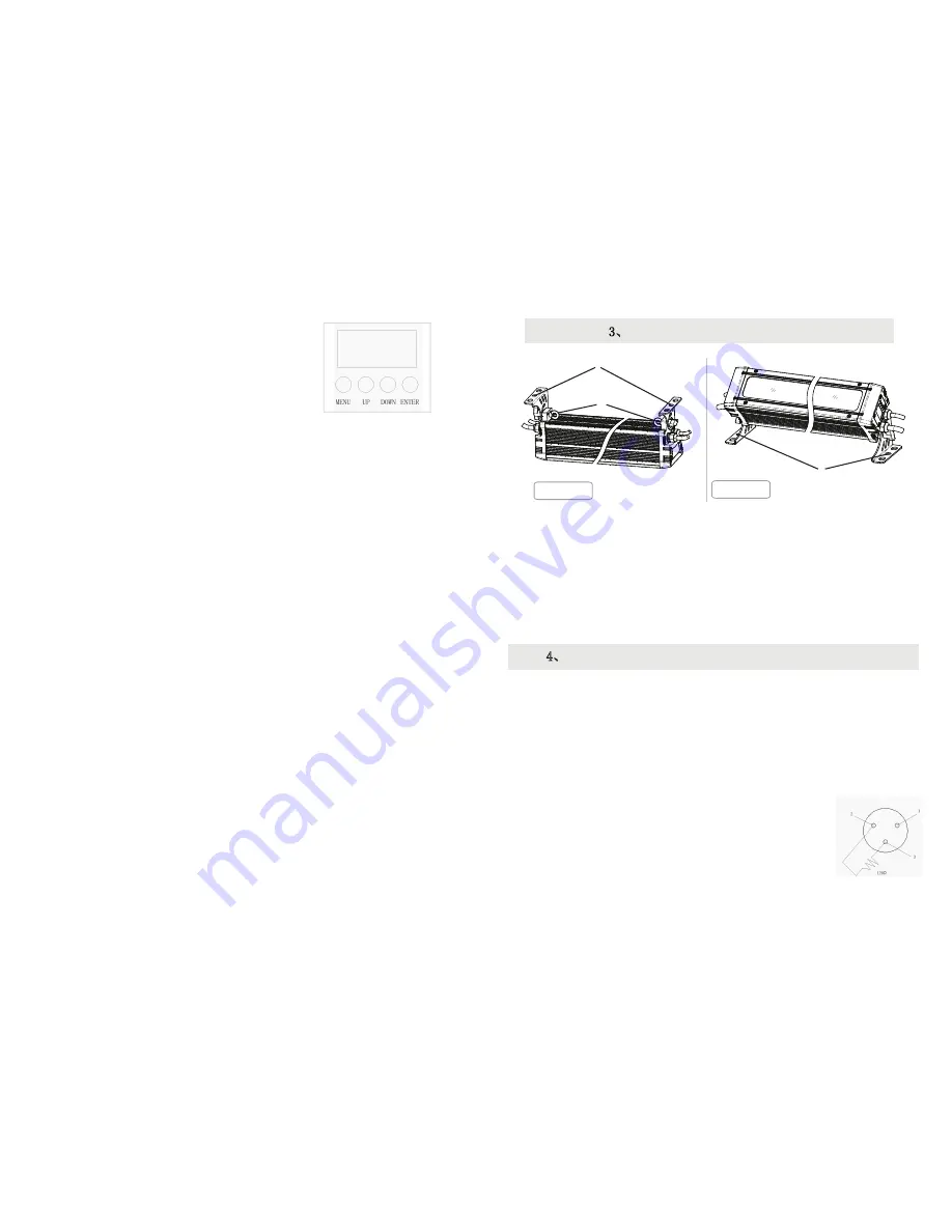
The lighting can be hanged on the high place with using the lamp hooks (as showed in
picture 1). Use the safety cord provided to pass through the bottom safe ring and
hang it as a second safety fixing.
The lighting also can place on the ground and make sure balance stand ,as showed in
picture 2.
Note:
Ensure support loading ability at least 10 times more than product weight,and make
sure lighting be firmly installed.
The lighting must be installed by the qualified personnel. Please install it at the
place where no one goes through.
4、
POWER SUPPLY-CONTROL SIGNAL CONNECTIONS
Make the XLR signal line connect with the lighting, one port connects with the output port of
lighting, another one connects with the input port of another lighting.
Due to the output and input of the lighting keep connecting all the time, so the DMX circuit
still can be keep connecting when the power of certain unit occurs turn-off.
XLR signal line only can be used in series connection pattern(the amount of the lighting can
not be more than 32 PCS), not available in parallel connection pattern. Must add a signal
amplifier if the length of signal line exceeds 60M between controller and lighting or between
two lightings.
In the controller mode, at the last fixture in the chain, the DMX output
has to be connected with a DMX terminator.
The DMX terminator is
simply a connector with a resistor about
120
Ω
(
OHM
)connected
across pins 2 and 3 of the
Canon
plug(please see the picture
in the right).
It can prevent the noise and reflection caused by DMX
512 signal during transmission.
3、
LIGHTING INSTALLATION
5.1
BUTTON OPERATION
1)
MENU
:
To return to the previous menu.
2)
ENTER
:
Enter to the next menu or save.
3)
UP
:
Menu selection or increasing the parameter.
4)
DOWN
:
Menu selection or decreasing the parameter.
5.2
DMX ADDRESS CODE SETTING
1)
Press the
【
ENTER
】
button in
【
ADDR
】
menu, then enter to the DMX address code setting.
2)
Press the
【
UP/DOWN
】
button to select
【
1-512
】
numerical value.
3)
Press the
【
ENTER
】
button to escape and save.
5.3
STATIC SETTING
1)
Press the
【
ENTER
】
button in
【
STAT
】
menu, then enter to the static setting.
2)
Press the
【
UP/DOWN
】
button to select
【
RED1
】,
【
GREEN1
】……【
WHITE3
】
and
【
SHUT
】
.
3)
Press the
【
UP/DOWN
】
button to set up the
【
0-255
】
numerical value.
4)
Press the
【
ENTER
】
button to escape and save.
5.4
COLOR CAST CALIBRATION SETTING
1)
Press the
【
ENTER
】
button in
【
CAL
】
menu, then enter to the color cast calibration setting.
2)
Press the
【
UP/DOWN
】
button to select
【
RED
】,【
GREEN
】,【
BLUE
】,【
WHITE
】
3)
Press the
【
UP/DOWN
】
button to set up the
【
0-255
】
numerical value.
4)
On the
【
USE
】
interface, pressing
【
ON
】
button means valid, otherwise
【
OFF
】
button invalid.
5)
Press the
【
ENTER
】
button to escape and save.
5.5
CHANNEL MODE SETTING
1)
Press the
【
ENTER
】
button in
【
CHMD
】
menu, then enter to the channel mode setting.
2)
Press the
【
UP/DOWN
】
button to select
【
18CH
】,【
10CH
】,【
7CH
】,【
5CH
】,【2CH】
3)
Press the
【
ENTER
】
button to escape and save.
5.6
DIMMING MODE SETTING
1)
Press the
【
ENTER
】
button in
【
DIM
】
menu, then enter to the dimming mode setting.
2)
Press the
【
UP/DOWN
】
button to select
【
OFF
】,
【
DIM1
】,【
DIM2
】,【
DIM3
】
and
【
DIM4
】
3)
Press the
【
ENTER
】
button to escape and save.
5.7
DISPLAY SETTING
1)
Press the
【
ENTER
】
button in
【
DISY
】
menu, then enter to the display setting.
2)
Press the
【
UP/DOWN
】
button to select
【
ON
】,
【
2 MINITES OFF
】
3)
Press the
【
ENTER
】
button to escape and save.
5.8
RUN THE AUTO-RUN, AUTO-PROGRAMMING PROGRAM
Illustrations:
When pressing the【ON】button which means valid on the【USE】
interface, the actual output value of RED,GREEN,BLUE,WHITE is output in
accordance with the percentage which the color cast calibration value divides 255.
Illustrations
:When setting【OFF】 in【DIM】menu, there will be no delay dimming
effect. The dimming speed of DIM1-DIM4 is from fast to slow. It will be set【OFF
】automatically in【DIM】menu when showing the shutter effect.
1)Press the【ENTER】button in【AUTO】menu, then enter to the running the auto-run,
auto-programming program.


