DLC170 Function Modules Installation and Operations Manual
17
Understanding and Using the DLC170AD
Figure 11.
DLC170AD Video Gain and Equalization Potentiometers
To adjust the video gain and cable equalization, perform the following tasks:
1. Connect the source video cable to the video input BNC connector (VIDEO IN) located on the rear panel.
2. Connect a test pattern generator with a multi-burst test pattern to the source end of the video cable.
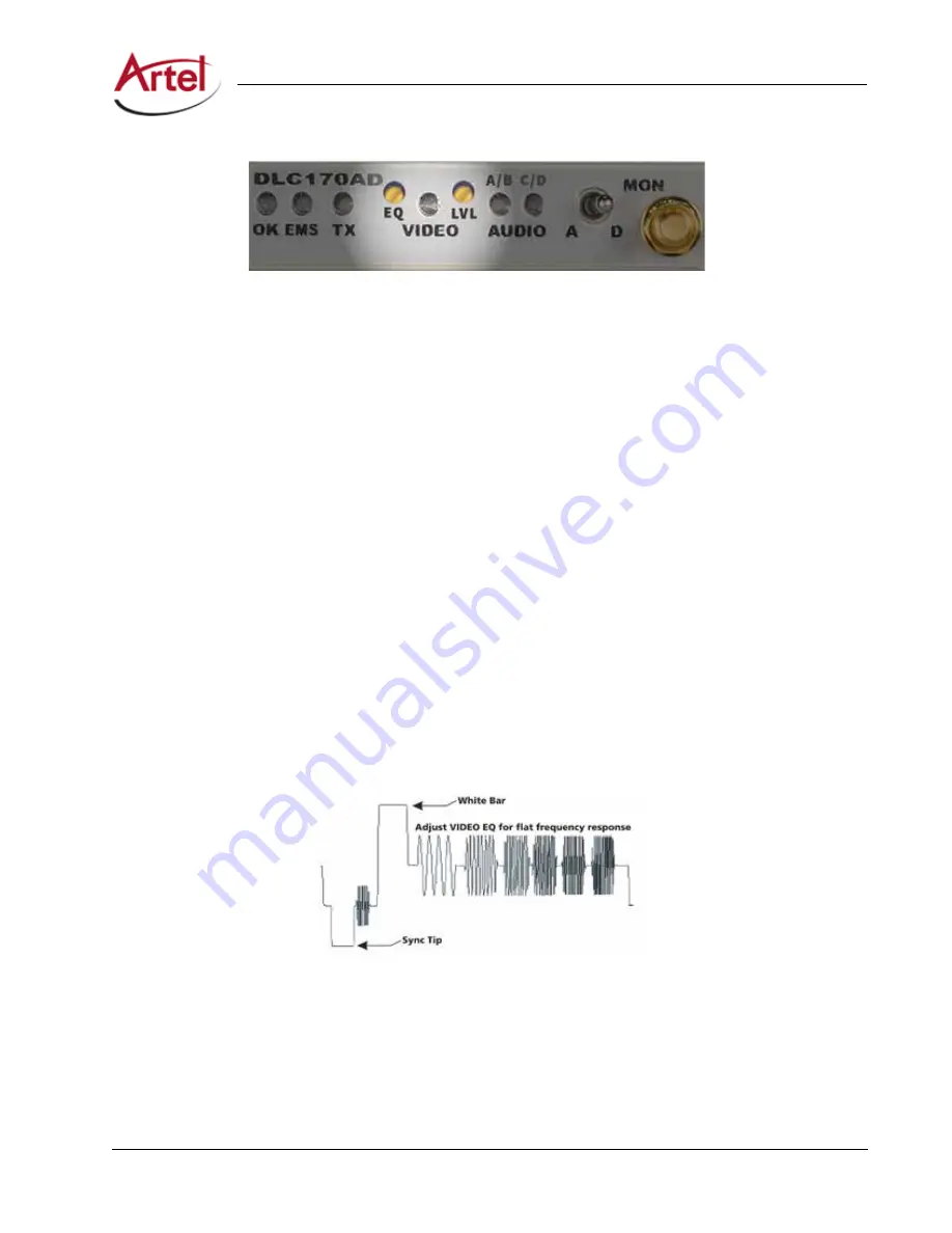
illustrates a multi-burst video test pattern.
3. Connect a calibrated video waveform monitor or vector scope terminated with 75 R to the monitor jack
(MON) located on the front panel.
4. Set the monitor source select switch located on the front panel to analog video (A).
5. Set the cable equalization by turning the EQ potentiometer until the signal attains a flat frequency
response (the frequency bursts are of the same amplitude as shown in
). Adjust the EQ
potentiometer as follows:
•
Decrease the amount of cable equalization—Turn the potentiometer counterclockwise.
•
Increase the amount of cable equalization—Turn the potentiometer clockwise.
If cable equalization is not required, skip ahead to Step 6.
6. Adjust the video input level by turning the LVL potentiometer until you achieve a 1 V peak-to-peak
difference from the sync tip to the white bar as measured from the video monitor jack (MON). Adjust the
LVL potentiometer as follows:
•
Increase the signal level—Turn the VIDEO LVL potentiometer clockwise.
•
Decrease the signal level—Turn the LVL potentiometer counterclockwise.
Figure 12.
Multi-Burst Video Test Pattern


