background image

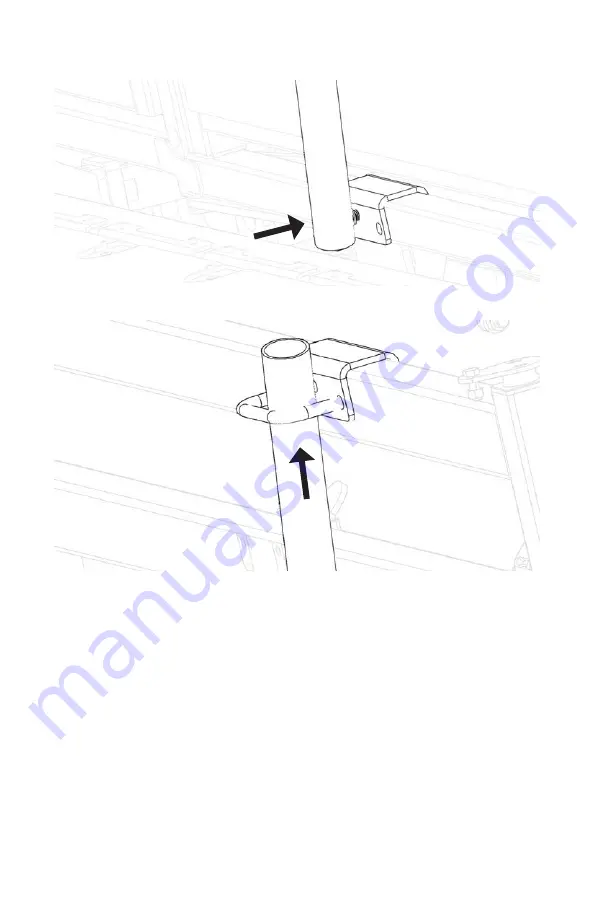
Attach the clipping rail to the bottom bracket.

Insert the clipping rail into the top bracket.

Adjust clipping rail position to your preference. Tighten bolts to secure. 

Safety Precautions: 
1.  Ensure the clipping rail is installed and secured correctly before running cattle through  


the crush.  

31 | Q-POWER 107 SERIES ADD-ONS

Summary of Contents for Q-POWER 107 Series

Page 1: ...Q POWER 107 SERIES MOBILE WORKING SYSTEMS 01530 632002 cs arrowquip com arrowquip co uk PRODUCT MANUAL 1078 10718 10708 LEFT RIGHT OCTOBER 2021...

Page 2: ...RST ROAD USE AND AFTER EACH WHEEL REMOVAL DO NOT REPAIR THE CRUSH OR GO INTO THE CRUSH WHEN HYDRAULICS ARE IN OPERATION THIS CAN RESULT IN INJURY TO THE WORKER UNPLUG THE MOTOR BEFORE PERFORMING ANY N...

Page 3: ...s 28 3rd Generation Q Catch Head Scoop 28 Sheeted Sternum Bar 30 Clipping Rail 31 Hydraulic Head Sweep 32 Easy Flow Race 32 Adjusting the Easy Flow Race 32 Using the Removable Panels 33 Using the Emer...

Page 4: ...njury or damage to persons cattle or property Arrowquip has taken precautions in the design and manufacturing of this product to ensure that it is safe and user friendly Therefore user must assume all...

Page 5: ...or around the equipment where cattle and operator will be 4 Please ensure that all hydraulics work properly before putting cattle through the crush 5 Please make sure that all hydraulic hoses are pro...

Page 6: ...FOR MANUAL JACKS Your unit will either come with manual or hydraulic jacks with both represented in this manual For manual jack control refer below REFERENCE FOR FORCING PEN INSTRUCTIONS Use this as...

Page 7: ...oose if you are operating the front or back jacks Refer to decal for directions 2 When crush is not attached to a vehicle lower to the ground for safety 3 Only lift the unit from firm level ground 4 N...

Page 8: ...If you have any questions please contact Client Care at 01530 632002 for assistance 5 TRANSPORTING THE Q POWER 107 SERIES MOBILE WORKING SYSTEM x...

Page 9: ...POWER 107 SERIES MOBILE WORKING SYSTEM 6 TO LOWER THE UNIT FOR USE Removing Tires 1 Extend front jack to support crush using UP button front jack handle 2 Detach crush from towing vehicle 3 Remove hi...

Page 10: ...ng DOWN button front jack handle until the crush rests on the ground 5 Remove front jack and place aside 7 TRANSPORTING THE Q POWER 107 SERIES MOBILE WORKING SYSTEM CRUSH SECTION MUST BE FLAT ON THE G...

Page 11: ...G SYSTEM 8 6 Extend rear jacks using UP button rear jack handle until tires are 1 off the ground 7 Remove tires 8 Retract rear jacks to set the unit on the set the unit on the ground until they stop u...

Page 12: ...OPERATING THE Q POWER 107 SERIES PAGE 27 UNFOLDING THE COLLAPSIBLE FORCING PEN APPLICABLE FOR 10718 10718 BF 10708 10708 BF MODELS 1 Remove the pin and pull out the bottom joiner bar Secure with the...

Page 13: ...CING PENS For 3E BudFlow forcing pens continue with these steps APPLICABLE FOR 10718 BF AND 10708 BF MODELS 1 Set aside panel 4 and joiner bar C TRANSPORTING THE Q POWER 107 SERIES MOBILE WORKING SYST...

Page 14: ...2 Unfold panels 1 3 and attach to the bottom joiner bar 3 Attach panel 4 to panel 3 11 TRANSPORTING THE Q POWER 107 SERIES MOBILE WORKING SYSTEM...

Page 15: ...C D to panels 1 2 3 and 4 as shown TIP Lower the unit to line up top joiner bars with panels 5 Fold out the 3E door and secure with joiner bar E Set aside transport pins TRANSPORTING THE Q POWER 107 S...

Page 16: ...OR 10718 AND 10708 STANDARD FORCING PEN MODELS 1 Unfold panels 1 3 and attach to the bottom joiner bar 2 Connect top joiner bars A B and C to panels 1 2 and 3 as shown TIP Lower the unit to line up to...

Page 17: ...unctioning properly All latches on doors gates and panels are functioning properly All joiner bars are locked into place When applicable all add ons are properly installed and functioning TRANSPORTING...

Page 18: ...BF proceed to FOLDING THE COLLAPSIBLE FORCING PEN FOLDING THE COLLAPSIBLE FORCING PEN 3E BUDFLOW FORCING PENS For 3E BudFlow forcing pens continue with these steps APPLICABLE FOR 10718 BF AND 10708 BF...

Page 19: ...TRANSPORTING THE Q POWER 107 SERIES MOBILE WORKING SYSTEM 16 2 Return joiner bar E to its holder and secure with the pin 3 Set aside panel 4 and joiner bars C D...

Page 20: ...17 TRANSPORTING THE Q POWER 107 SERIES MOBILE WORKING SYSTEM 4 Latch the swing gate to the left hand side of the rolling door 5 Push the crowd gate against the swing gate...

Page 21: ...6 Return top joiner bars A B C D to their respective holders 7 Fold panels 1 3 inward as shown TRANSPORTING THE Q POWER 107 SERIES MOBILE WORKING SYSTEM 18 FLIP BAR...

Page 22: ...IES MOBILE WORKING SYSTEM 8 Return panel 4 to transport position and secure with the pins 9 Secure the panels with the ratchet strap and transport chain as shown TIGHTEN THE RATCHET STRAP TO PREVENT P...

Page 23: ...ract the bottom joiner bar and secure with the pin 11 Proceed to INSTALLING TIRES PAGE 23 STANDARD FORCING PENS FOR STANDARD FORCING PENS CONTINUE WITH THESE STEPS APPLICABLE FOR 10718 AND 10708 STAND...

Page 24: ...21 TRANSPORTING THE Q POWER 107 SERIES MOBILE WORKING SYSTEM 2 Return top joiner bars A B C to their respective holders Secure joiner bar C with the transport pin 3 Fold panels 1 3 inward as shown...

Page 25: ...transport chain as shown 5 Retract the bottom joiner bar and secure with the pin 6 Proceed to INSTALLING TIRES TRANSPORTING THE Q POWER 107 SERIES MOBILE WORKING SYSTEM 22 TIGHTEN THE RATCHET STRAP T...

Page 26: ...r jacks to lift the unit off the ground until it is high enough to attach the tires Using the UP button rear jack handle 2 Attach tires 3 Retract rear jacks using DOWN button rear jack handle until th...

Page 27: ...4 Attach front jack 5 Extend front jack using UP button front jack handle to lift chute 6 Install the hitch and secure with pin TRANSPORTING THE Q POWER 107 SERIES MOBILE WORKING SYSTEM 24 A B...

Page 28: ...just the hitch to the proper position for the vehicle if necessary 8 Retract front jack using DOWN button front jack handle until it stops All loose parts are secured including panels and joiner bars...

Page 29: ...LE CRUSH This section contains Q Power 107 Series Hydraulic Squeeze Crush Assembly Operating the Q Power 107 Series Power Failure Cold Start Q Power 107 Series Add Ons USING THE Q POWER 107 SERIES CAT...

Page 30: ...animal enters the crush 2 Open rear gate for the animal to enter the cattle crush enclosure 3 Close rear gate 4 Open yoke gate slightly more than the neck size of the animal to tempt the animal to sti...

Page 31: ...ush please follow the instructions below 1 Operate the hydraulic levers to allow fluid to flow out of the cylinders and release the pressure on the animal 2 Check to make sure that the animal is free...

Page 32: ...e use detent pin to hold the head scoop in place Maintenance 1 Add grease through the grease nipples as needed 2 Every 6 months a Check bolts to ensure they are tightened properly b Spray brake cleane...

Page 33: ...sternum bar is installed correctly before running cattle through the crush Safety Precautions 1 Remove the sternum bar when working calves CLIPPING RAIL Installation 1 Place both brackets on the crus...

Page 34: ...clipping rail into the top bracket 4 Adjust clipping rail position to your preference Tighten bolts to secure Safety Precautions 1 Ensure the clipping rail is installed and secured correctly before r...

Page 35: ...RACE This section contains Adjusting the Easy Flow Race Using the Removable Panels Using the Emergency Exit Scale Platform Installation Rolling Door Switch ADJUSTING THE EASY FLOW RACE Safety latches...

Page 36: ...be configured in multiple positions allowing you to control what cattle see in the raceway Additional panels can be added as desired 1 Unscrew bolts on both ends to release the panel 2 Remove the pan...

Page 37: ...e 5 Release the slam latches on the panel to be lowered 6 Lower the exit panel to the ground slowly with the rope 7 Assist the animal to exit the race and provide care as necessary 8 Once the animal i...

Page 38: ...1 Adjust the race width to the narrowest setting 2 Lift the side panel and set the latch above the race bow Repeat step for the opposite side panel 35 SCALE PLATFORM INSTALLATION WARNING THE PANELS AR...

Page 39: ...3 Slide Scale Platform underneath SCALE PLATFORM INSTALLATION 36...

Page 40: ...ning cattle through the unit ROLLING DOOR SWITCH REQUIRED TOOLS 9 16 wrench 2x 3 4 wrench LEFT HAND TO RIGHT HAND Switching from Left hand to Right hand operation shown For Right hand to Left hand ope...

Page 41: ...1 Remove rolling door handle slider 2 Remove the rolling door from the main frame ROLLING DOOR SWITCH 38...

Page 42: ...3 Remove the rolling door track plate and switch to the opposite side 39 ROLLING DOOR SWITCH B A...

Page 43: ...4 Remove the rolling door bumpers and move to the opposite side 5 Install the rolling door and secure to the main frame 6 Install the rolling door handle slider on the right hand side...

Page 44: ...Using the Standard Forcing Pen OPERATING GUIDELINES For instructions on how to fold and unfold your cattle forcing pen go to TRANSPORTING THE Q POWER 107 SERIES MOBILE WORKING SYSTEM ON PAGE 2 USING T...

Page 45: ...de cattle into the race RECOMMENDED MAINTENANCE This section contains Maintenance Safety Cattle Crush Maintenance Hydraulic Maintenance Power Pack Maintenance Hydraulic Jack Maintenance Battery Mainte...

Page 46: ...T repair the crush or go into the crush when hydraulics are in operation This can result in injury to the worker Unplug the motor before performing any necessary repairs or inspection REGULAR MAINTENA...

Page 47: ...hydraulic systems Replace oil frequently to prevent damage to your hydraulic jacks and keep them working safely and reliably POWER PACK MAINTENANCE Inspect the entire unit Ensure all moving component...

Page 48: ...ngth force For example a force of 90 pounds applied at the end of a wrench on foot long will yield 90 ft lbs of torque A torque wrench is the best method to assures the proper amount of torque is bein...

Page 49: ...te slam latches and pivot points with WD 40 Dry Lube POWER PACK Contact your Electrician for assistance with any Power Pack issues For additional information download your Power Pack Manual here Q POW...

Page 50: ...g it is likely the battery may be low and in need of charge c Use an AGM Battery Charger to charge the unit or boost by attaching jumper cables to the charging lugs on the outside of the box i Arrowqu...

Page 51: ...ufacturer defect during the Warranty Period at their sole discretion This excludes defects resulting from normal wear and tear or product misuse Warranty does not cover corrosion NOTE Any modification...

Page 52: ...Printed in Canada October 2021 If you have any questions regarding your product or require assistance please contact Arrowquip s Client Care Team at 01530 632002 or by email at cs arrowquip com...

Reviews: