Assembly Instructions
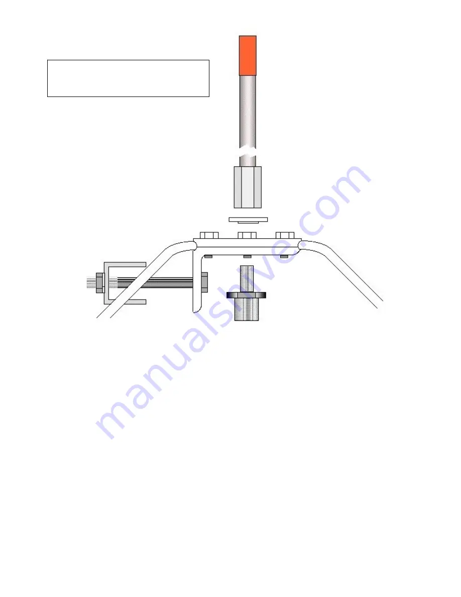
Using a 7/16” wrench, loosen the three 1/4” bolts and insert the four ground radials. Be sure they are inserted all the way in and
bottomed out. Snug the four bolts making sure the radials are angled down the same. After the radials are seated correctly, tighten the
four bolts.
Install the 55” element in the center hole of the Assembly / Mounting Bracket with the nylon shoulder washer under the element as
shown. Tighten with 5/8" wrench.
SWR is basically a way of testing the impedance of your Antenna System. The Antenna System is two parts.
1. Coax and connectors.
2. Antenna.
Before you can test or tune the Antenna, you have to test the other 1/2 of the system first, the Coax &
Connectors.
Brand New Coax can be Defective or Damaged.
To test the Coax you will need a 50 ohm Dummy Load and an SWR Meter or Antenna Analyzer.
Note: Some of the MFJ 269 Analyzers do not work right. - - (eHam reviews on the MFJ269) - - The MJF 259B
works Great.
Connect the Dummy Load to the end of the coax instead of the Antenna. Connect SWR Meter or Antenna
Analyzer to the other end. Check the SWR on all frequencies. SWR should be 1.0:1 on all frequencies. If the
SWR is not 1.0:1 or if the SWR varies with frequency, then the Coax is Not up to the task.
Important: Some Coax can test fine on VHF but not at UHF.
Also a known problem with some remote Antenna Switches.
Remember the ground radials must be
attached and secure before installing the
vertical element.
Caution
: Do NOT over-tighten the 55”
element. 30 ft./lb. max.
Coupling Nut ---------
Shoulder Washer------
------3/8 x 24
------SO-239
55” Element ---------
--------- Assembly / Mounting Bracket
Ground Radial --------
Saddle ---------


