Chapter 5
:
Installing and Connecting your Telephony Modem
Release 8 STANDARD 1.3 August 2016
Touchstone TM822G Telephony Modem User Guide
© 2011-2016 ARRIS Enterprises LLC. All Rights Reserved.
25
5.
Online:
indicates internet data transmission status.
6.
US:
indicates upstream connectivity. It may be yellow or green to indicate the connection
speed.
7.
DS:
indicates downstream connectivity. It may be yellow or green to indicate the
connection speed.
8.
Power:
indicates whether AC power is available to the unit.
Rear Panel
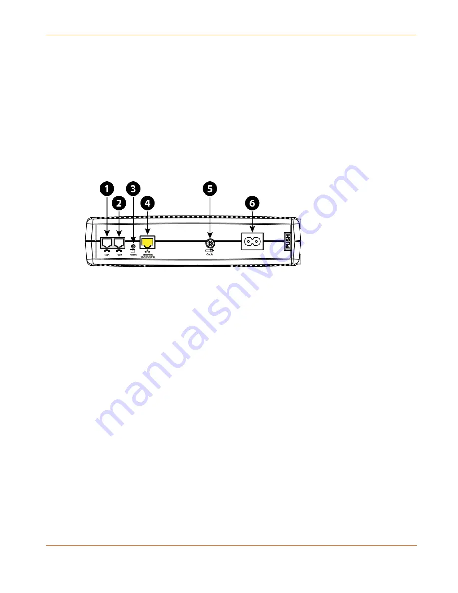
The rear of the Telephony Modem has the following connectors and controls.
1.
Tel 1:
connector for the first phone line.
2.
Tel 2:
connector for the second phone line.
3.
Reset button:
resets the Telephony Modem as if you power cycled the unit. Use a pointed
non-metallic object to press this button.
4.
Ethernet:
connector for use with a computer LAN port.
5.
Cable:
connector for the coaxial cable.
6.
Power:
connector for the power cord.
Selecting an Installation Location
There are a number of factors to consider when choosing a location to install your Telephony
Modem:
Is an AC outlet available nearby? For best results, the outlet should not be switched and
should be close enough to the Telephony Modem that extension cords are not required.
Is a cable jack available? For best performance, keep the number of splitters between the
jack and cable drop to a minimum. Each splitter attenuates (reduces) the signal available
to the Telephony Modem. A large number of splitters can slow down the Internet
connection and even affect your telephone service.
Can you easily run cables between the Telephony Modem’s location and the phones?
If you are connecting devices to an Ethernet port, can you easily run cables between the
Telephony Modem’s location and those devices?


