background image

30

Multifunction LCD Digital Counter

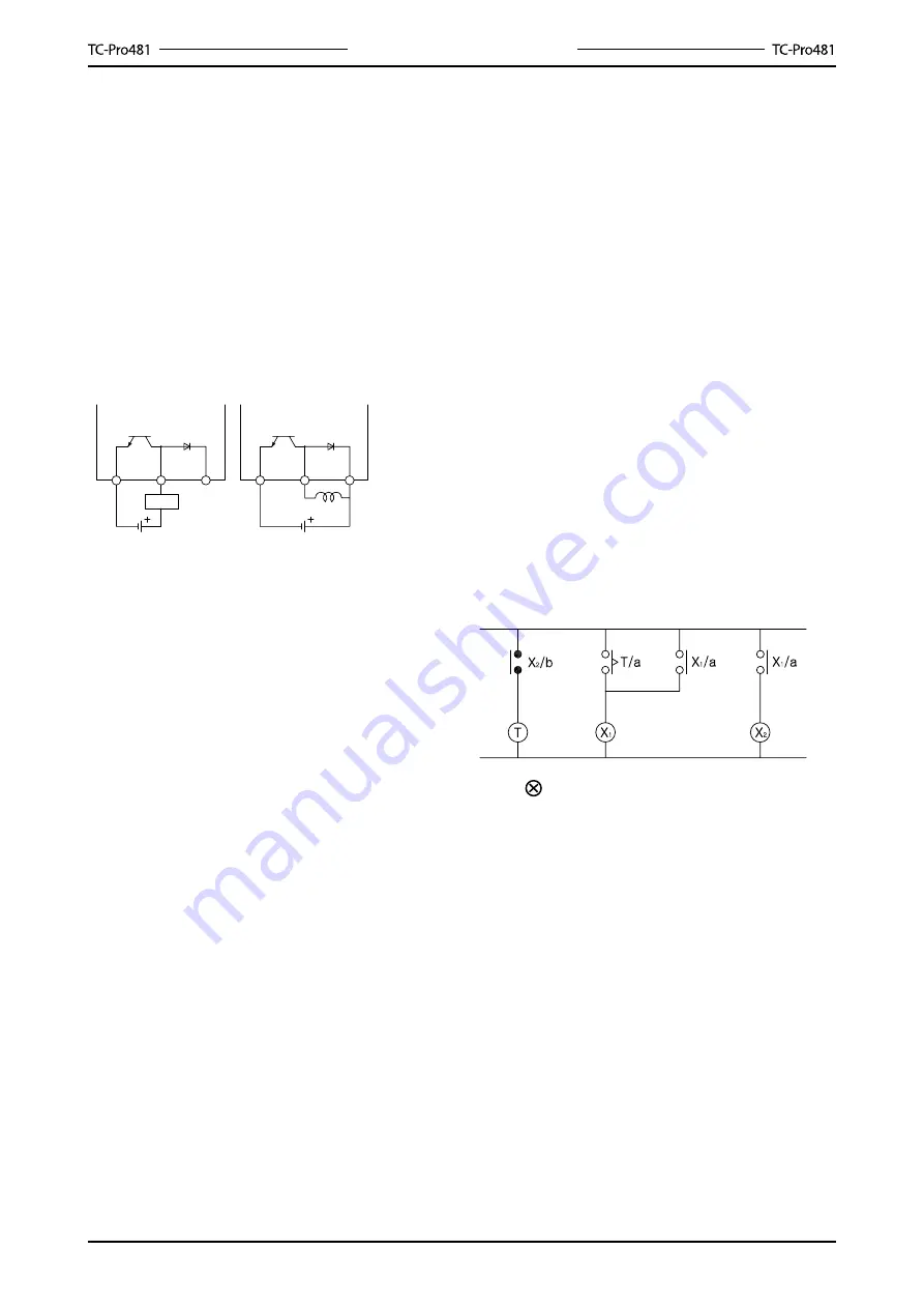
Transistor Output

The transistor output of TC-Pro is insulated from the 

internal circuitry by a photocoupler, so the transistor 

output can be used as both NPN and PNP output.

The diode connected to the collector of the output 

transistor is used to absorb inverted voltage that is 

generated when an inductive load is connected to 

TC- Pro.

NPN output

PNP output

Timer 

Timer 

Power for load

Power for load

Inducted load

Changing the set values 

When  changing  the  set  value  during  a  timing 

operation, the output will turn ON if the set value 

is  changed  as  follows  because  of  the  use  of  a 

constant read-in system:

Elapsed time(up) mode: present value≥set value

Remaining time(DOWN) mode: elapsing time≥ set 

value(the present value is set to 0)

Note: when in the remaining time mode, the amount 

the set value is changed is added to or subtracted 

from the present value.

Connection 

Make sure that wiring is correct.

Mounting

Tighten  two  mounting  screws  on  the  adapter. 

Tighten them alternately, a little at a time, so as to 

keep them at an equal tightness. 

TC-Pro  panel  surface  is  water-resistant.  In 

order  to  prevent  the  internal  circuit  from  water 

penetration through the space between the TC-

Pro  and  operating  panel,  attach  a  waterproof 

packing between TC-Pro and installation panel 

and secure the waterproof packing with the BK-62              

flush-mounting adapter.

Operation environment

Use the product within the rating specified for 

submerging in water and exposure to oil.

Do not use in location affected by excessive 

vibration or shock

Do not use the product in locations subject to 

dust, corrosive gases, or direct sunlight.

Separate the input signal devices, input signal 

cables,  and  the  product  from  the  source  of 

noise or high-tension cables producing noise.

Separate  the  product  from  the  source  of 

static electricity when using the product in an 

environment where a large amount of static 

electricity is produced (e.g. forming compounds, 

powders, or fluid materials being transported by 

pipe). 

Organic solvents (such as paint thinner), as well 

as very acidic or basic solutions might damage 

the outer casing of the TC-Pro. 

Use the product within the rating specified for 

temperature and humidity.

Do  not  use  the  product  in  locations  where 

condensation may occur due to high humidity 

or where temperature changes are severe.

Store  at  the  specified  temperature.  If             

TC-Pro has been stored at a temperature of 

less than -0

, allow TC-Pro to stand at room 

temperature for at least 3 hours before use.

Note:    auxiliary relay (e.g. MY relay)

Insulation

There is basic insulation between power supply and 

output terminals. 

Input and output terminals are connected to devices 

without exposed charged parts. 

Input  and  output  terminals  are  connected  to 

devices with basic insulation that is suitable for the 

maximum operating voltage.

Summary of Contents for TC-Pro481 Series

Page 1: ...Ver 3 0...

Page 2: ...PNP NPN switchable DC voltage input Finger safe terminals screw terminal block models Three language instruction manual Applied to connect PC HMI Contents Model Number Structure 2 Speci cations 3 Nom...

Page 3: ...r 1 5m Cable CAB 090A485 9 pin Female D sub cable for RS 422 connector 1 5m Cable CAB 090A422 9 pin male D sub adapter for CAB 090A232 CAB 090A485 CAB 090A422 ADP 090401 9 pin Female D sub cable for R...

Page 4: ...input Minimum reset input signal width 1 or 20ms selectable common setting for all inputs Reset system External manual and automatic reset internal according to C R P and Q mode operation Output mode...

Page 5: ...ons min 5 A at 250 VAC resistance load EMC EMI Emission Enclosure Emission AC mains EMS Immunity ESD Immunity RF interference Immunity Conducted Disturbance Immunity Burst Immunity Surge Immunity volt...

Page 6: ...d resets the present value the batch count value and outputs Dual counter Resets the CP1 present value CP2 present value dual count value and outputs tachometer Maintains the measured value and output...

Page 7: ...rformed during reset 1 input The reset indicator is lit during reset 1 input 2 Total Reset or Reset 2 see note 2 When used as 1 stage 2 stage counter Does not operate Not used When used as a total and...

Page 8: ...P1 CP2 Reads counting signals CP2 input is not used RESET1 RESET2 Holds the measurement value and outputs CP2 input is not used The reset indicator is lit during hold Outputs OUT1 OUT2 Outputs signals...

Page 9: ...stage 2 stage total batch dual counter tachometer selection mode counter will be reset 1 stage counter setting mode See Run Mode on page 10 2 stage counter setting mode See Run Mode on page 10 Total...

Page 10: ...munication on off Set the transmision speed with key Set the parity check with key Set the date bit with key Set the stop bit with key Set the Station address HEX with key Set communication on off wit...

Page 11: ...The key protection indicator is lit while the key protection switch is set to ON See note 3s min See note 3s min K P ON Setting mode K P OFF Setting mode Run Mode K P Setting Mode Level Meaning Changi...

Page 12: ...99s 000 001 001 000 999 999 See note 5 See note 5 Note 5 displayed only when the input mode is UP DOWN A B or C N F C R K 1 P Q A K 2 D L H 30Hz 5KHz 20ms 1ms no decimal point one digit after decimal...

Page 13: ...mode If the output time is set to 0 00 HOLD is displayed and outputs are held HOLD can not be set when the output mode is K 2 Counting speed cnts Set the maximum counting speed 30Hz 5KHz for CP1 and...

Page 14: ...ating mode is SUB Dual count value Set dual count value When the dual count value reaches the dual count set value signals are output according to the specified output mode CP1 CP2 present value Show...

Page 15: ...nput mode UP DOWN C Quadrature input mode Note If the configuration selection is set to dual count CP1 and CP2 input will operate in the same way as the count input CP1 of UP increment mode The meanin...

Page 16: ...e a t o n e s h o t operation OUT1 self holding output turns OFF after the OUT2 o n e s h o t o u t p u t time The OUT1 one s h o t o u t p u t t i m e is independent of OUT2 R The present value displ...

Page 17: ...value c o n t i n u e s t o increase decrease for the one shot output time but returns to the reset start status after the one shot output time has elapsed The outputs repeat one shot operation OUT1...

Page 18: ...value is reached OUT1 is held while the present value is less than or equal to set value 1 OUT2 is held while the present value is less than or equal to set value 2 A The display continues to increas...

Page 19: ...imes the count value returns to 0 when it reaches the full scale limit The batch counter continues after count completion Batch output is held until batch counter reset is input When the batch counter...

Page 20: ...P2 input Note Counting is not possible for CP1 during reset 1 input CP2 will not be affected The dual count value will be calculated based on a CP1 present value of 0 Counting is not possible for CP2...

Page 21: ...measured value initialized and output turned OFF on returning to run mode The characters displayed in reverse video are the initial values Set each setting item with the Key 30Hz 10KHz no decimal poi...

Page 22: ...ttering can be prevented using average processing simple averaging Average processing can be set to one of four levels no average processing 2 times i e the average of 2 measurement values 4 times 8 t...

Page 23: ...s Measurement value Measurement value OUT1 set value Measurement value OUT2 set value Displays the currently measured value OUT1 OUT2 set value Set OUT1 set value and OUT2 set value The measurement va...

Page 24: ...t value OUT set value Measurement value OUT2 set value OUT1 set value OUT2 set value Measurement value OUT2 set value Measurement value OUT1 set value OUT2 set value Measurement value OUT1 set value O...

Page 25: ...ions without Flush Mounting Adapter Note M3 terminal screw effective length 8mm Dimensions with Flush Mounting Adapter Panel Cutouts Note The mounting panel thickness should be 1 5 mm To allow easier...

Page 26: ...nter Dimensions Note all units are in millimeters unless otherwise indicated Dimensions without DIN Track Mounting Adapter Note M3 terminal screw effective length 8mm Dimensions without DIN Track Moun...

Page 27: ...er separately Waterproof Packing Flush Mounting Adapter End Plate CABC 44 Mounting Track PR 43 BK 6 0F A order separately ADP 090401 apdater changing 4 into 9 PIN Panel Protective Cover Communication...

Page 28: ...tion to a voltage output sensor Gate CP1 Reset 2 Reset 1 Signal CP2 External voltage External voltage When SW is pressed the transistor is ON that shows the input has response Contact Input Gate CP1 R...

Page 29: ...onnection to NPN open collector output sensor Gate CP1 Reset 2 Reset 1 Signal CP2 External voltage External voltage When SW is pressed the transistor is ON that shows the input has no response No cont...

Page 30: ...is possible unstable or impossible Turn the power ON and OFF using a relay with a rated capacity of 10A minimum to prevent contact deterioration due to inrush current caused by turning the power ON an...

Page 31: ...uit from water penetration through the space between the TC Pro and operating panel attach a waterproof packing between TC Pro and installation panel and secure the waterproof packing with the BK 62 f...

Page 32: ...put signal width Decimal point position Prescale value NPN PNP input mode Key protection level Parity check Transmission speed Power ON Run mode Function setting mode Communication setting mode Presen...

Page 33: ...set value Tachometer output mode Counting speed Decimal point position Prescale value Average processing Auto zero time Startup time Key protection level NPN PNP input mode Communication setting mode...

Page 34: ...44 192 288 384 576 96 Bps Parity Check pari none odd even none Date bit data 8bit 7bit 8bit bits Stop bit stop 1bit 2bit 1bit bit Station address Hex addr 01 to ff 01 Communication OFF cosh on off on...

Page 35: ...e note 1 Total and preset counter Parameter name parameter Setting range Default value Unit Set value Screen 1 Present value 99999 999999 000000 Set value 1 000000 999999 For conditions other than tho...

Page 36: ...ing mode Parameter name parameter Setting range Default value Unit Set value Input mode cntm up down ud a ud b ud c See note 1 up Dual count calculating mode caln add sub See note 1 add Output mode ou...

Page 37: ...000000 999999 000000 000000 999999 000000 Function setting mode Parameter name parameter Setting range Default value Unit Set value Tachometer output mode totm hilo area hihi lolo hilo Counting speed...

Page 38: ...Comparison Table...
Reviews: