Page 2 of 8
PD10P-X
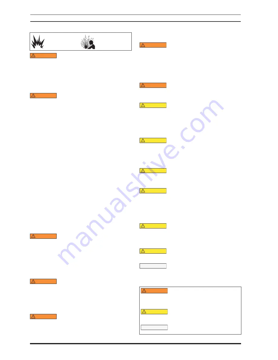
EXCESSIVE AIR PRESSURE
STATIC SPARK
HAZARDOUS MATERIALS
HAZARDOUS PRESSURE
WARNING
EXCESSIVE AIR PRESSURE. Can cause per-
sonal injury, pump damage or property damage.
Do not exceed the maximum inlet air pressure as
stated on the pump model plate.
Be sure material hoses and other components are able
to withstand fluid pressures developed by this pump.
Check all hoses for damage or wear. Be certain dispens-
ing device is clean and in proper working condition.
WARNING
STATIC SPARK. Can cause explosion
resulting in severe injury or death. Ground pump and
pumping system.
Sparks can ignite fl ammable material and vapors.
The pumping system and object being sprayed must be
grounded when it is pumping, fl ushing, recirculating or
spraying fl ammable materials such as paints, solvents,
lacquers, etc. or used in a location where surrounding
atmosphere is conducive to spontaneous combustion.
Ground the dispensing valve or device, containers, hos-
es and any object to which material is being pumped.
Secure pump, connections and all contact points to
avoid vibration and generation of contact or static spark.
Consult local building codes and electrical codes for
specifi c grounding requirements.
After grounding, periodically verify continuity of
electrical path to ground. Test with an ohmmeter
from each component (e.g., hoses, pump, clamps, con-
tainer, spray gun, etc.) to ground to insure continuity.
Ohmmeter should show 0.1 ohms or less.
Submerse the outlet hose end, dispensing valve or
device in the material being dispensed if possible.
(Avoid free streaming of material being dispensed.)
Use hoses incorporating a static wire.
Use proper ventilation.
Keep inflammables away from heat, open flames and
sparks.
Keep containers closed when not in use.
WARNING
Pump exhaust may contain contaminants.
Can cause severe injury. Pipe exhaust away from work
area and personnel.
In the event of a diaphragm rupture, material can be
forced out of the air exhaust muffl
er.
Pipe the exhaust to a safe remote location when
pumping hazardous or infl ammable materials.
Use a grounded 3/8” minimum i.d. hose between the
pump and the muffl
er.
WARNING
HAZARDOUS PRESSURE. Can result in serious
injury or property damage. Do not service or clean pump,
hoses or dispensing valve while the system is pressurized.
Disconnect air supply line and relieve pressure from
the system by opening dispensing valve or device and
/ or carefully and slowly loosening and removing out-
let hose or piping from pump.
WARNING
HAZARDOUS MATERIALS. Can cause serious
injury or property damage. Do not attempt to return
a pump to the factory or service center that contains
hazardous material. Safe handling practices must comply
with local and national laws and safety code requirements.
y
y
y
y
y
y
y
y
y
y
y
y
y
y
y
y
Obtain Material Safety Data Sheets on all materials
from the supplier for proper handling instructions.
WARNING
EXPLOSION HAZARD. Models containing
aluminum wetted par ts cannot be used with
1,1,1-trichloroethane, methylene chloride or other
halogenated hydrocarbon solvents which may react
and explode.
Check pump motor section, fl uid caps, manifolds and
all wetted parts to assure compatibility before using
with solvents of this type.
WARNING
MISAPPLICATION HAZARD. Do not use
models containing aluminum wetted parts with food
products for human consumption. Plated parts can
contain trace amounts of lead.
CAUTION
Verify the chemical compatibility of the
pump wetted parts and the substance being pumped,
flushed or recirculated. Chemical compatibility may
change with temperature and concentration of the
chemical(s) within the substances being pumped,
fl ushed or circulated. For specifi c fl uid compatibility,
consult the chemical manufacturer.
CAUTION
Maximum temperatures are based
on mechanical stress only. Certain chemicals will
significantly reduce maximum safe operating
temperature. Consult the chemical manufacturer for
chemical compatibility and temperature limits. Refer
to PUMP DATA on page 1 of this manual.
CAUTION
Be certain all operators of this equipment
have been trained for safe working practices,
understand it’s limitations, and wear safety goggles /
equipment when required.
CAUTION
Do not use the pump for the structural
support of the piping system. Be certain the system
components are properly supported to prevent stress
on the pump parts.
Suction and discharge connections should be fl exible
connections (such as hose), not rigid piped, and should
be compatible with the substance being pumped.
CAUTION
Prevent unnecessary damage to the
pump. Do not allow pump to operate when out of
material for long periods of time.
Disconnect air line from pump when system sits idle
for long periods of time.
CAUTION
Use only genuine ARO replacement parts
to assure compatible pressure rating and longest
service life.
NOTICE
RE-TORQUE ALL FASTENERS BEFORE
OPERATION. Creep of housing and gasket materials
may cause fasteners to loosen. Re-torque all fasteners
to insure against fl uid or air leakage.
WARNING
=
Hazards or unsafe practices which
could result in severe personal injury,
death osr substantial property dam-
age.
CAUTION
=
Hazards or unsafe practices which
could result in minor personal injury,
product or property damage.
NOTICE
=
Important installation, operation or
maintenance information.
y
y
y
y
OPERATING AND SAFETY PRECAUTIONS
READ, UNDERSTAND, AND FOLLOW THIS INFORMATION TO AVOID INJURY AND PROPERTY DAMAGE.


