Installation and Maintenance
EHU-600 Series Humidifiers
14
13. Submittal Drawings
Chart 14:1 Dimensional Data
EHU-600
EHU-601
EHU-602
in
mm
in
mm
in
mm
"A"
Width
18
457
18
457
31
787
"B"
Height
23
584
28
1
/
2
724
28
1
/
2
724
"C"
Depth
11
1
/
2
292 13
11
/
32
339 13
11
/
32
339
"D"
Tank Drain (Side)
6
5
/
8
168
6
3
/
16
157
6
3
/
16
157
"E"
Tank Drain (Front)
10
5
/
16
262
8
1
/
4
210
8
1
/
4
210
"F"
Cabinet Drain 5/8" OD
N/A
N/A
11
1
/
2
292
18
457
"G"
Tank #2 Drain (Front)
N/A
N/A
N/A
N/A 21
3
/
16
538
"H"
Steam Outlet #1
12
1
/
2
318
11
1
/
2
292
11
1
/
2
292
"I"
Steam Outlet #2
N/A
N/A
N/A
N/A
13
330
"J"
Water Supply* (Side)
8
1
/
4
210
9
13
/
16
249
9
13
/
16
249
"K"
Water Supply* (Front)
15
1
/
2
394
3
5
/
16
84
3
5
/
16
84
"L"
Electrical Supply (Side)
3
1
/
8
80
2
51
2
51
"M"
Electrical Supply (Front)
4
1
/
2
114
2
1
/
2
64
2
1
/
2
64
"N"
Fan Height (EHF-2)
13
330
N/A
N/A
N/A
N/A
"N"
Fan Height (EHF-3)
16
406
Remote Installation Only
"P"
Front Clearance
18
457
24
610
24
610
"Q"
Left Clearance
4
102
24
610
24
610
"R"
Bottom Clearance
5
127
5
127
5
127
"S"
Right Clearance
4
102
4
102
4
102
* Water Supply Conn. 3/8" Compression.
Unit is designed to mount on 16" centers.
2 lag screws are provided for EHU-600.
2 lag screws & bracket are provided for EHU-601 & 602.
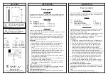
Figure 14-1 Model EHU-600
(Front and Side View)
Figure 14-2: Model EHU-601
Figure 14-3: Model EHU-602
(Front and Side View)
(Front View)
R
5/8'' O.D. Cabinet
Drain
3/4'' NPT
Tank Drain
1-1/2” I.D.
Hose Cuff
TANK DRAIN
1
Z\x
"
I.D.
Hose Cuff
3/4" NPT
Tank Drain
5/8” O.D.
Cabinet Drain


