


installation &
oper ating instructions
E.2 Series high efficiency
circulator
5
6
For
120 v
models:
Referring to
diagram 2
below, connect the
black, hot, (L) and white, neutral, (N) leads of the supply
wire to the black and white motor leads respectively inside
the terminal box. Connect the ground wire to any one of the
four green ground screws inside of the terminal box (use a
minimum
18
awg
wire size).
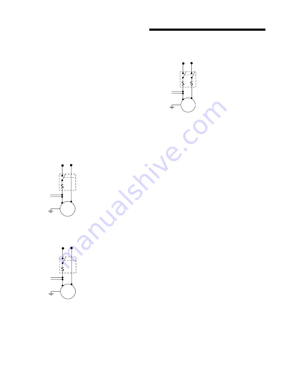
For
208/240/277
v models:
Referring to
diagram 3
below,
connect the black (
l1
) and blue (
l2
) leads of the supply
wire to the black and blue motor leads respectively inside
the terminal box. Connect the ground wire to any one of the
four green ground screws inside of the terminal box (use a
minimum
18
awg
wire size).
note:
For any voltage the brown and yellow wires are hard wired in
and should
not
be touched they are for the capacitor only and can
stop the motor from running.
diagram 2
120 v
installations
pump
motor
Pump motor
thermally protected
To auxilliary
control, if
required
Fusible disconnect
or circuit breaker
by others
L
N
Typical wiring diagram for
single phase,
120 v, 60 hz
power source
diagram 3
208/240/277 v
installations
pump
motor
Pump motor
thermally protected
To auxilliary
control, if
required
Fusible disconnect
or circuit breaker
by others
l1
l2
Typical wiring diagram for
a
single phase,
240 v, 60 hz
power source
b
three phase,
208/277 v, 60 hz
power source
diagram 4
230 v
installations
pump
motor
Pump motor
thermally protected
To auxilliary
control, if
required
Fusible disconnect
or circuit breaker
by others
l1
l2
Typical wiring diagram for
single phase,
230 v, 50 hz
power source
7
Replace the terminal box cover.
The motor is thermally protected for your safety so thermal
overload protection is not necessary. All that is required is a
fused plug or circuit breaker in the power line for short circuit
protection.
Electrical information can be found on the nameplate of
the motor.
3.0 start up
1
Before starting up the circulator, proper installation practice
recommends a thorough flush and draining of the hydronic
system, ensuring removal of all foreign materials. Fill the
system with clean water or glycol solution before starting.
2
Air must be completely vented from the system before
starting up the circulator.
If the system is not completely
vented of air and the circulator is allowed to run dry, the
mechanical seal will be damaged.
3
When the system has been completely filled and vented,
only then can the pump be started.
4.0 preventive maintenance – inspection
e.2 s
eries circulators are fitted with permanently lubricated
ball bearings and
do not
require lubrication.
Although Armstrong long-life circulators are designed to
provide years of worry-free service, it is good maintenance
practice to inspect the entire hydronic system periodically –
including the
e.2 s
eries circulator – for potential problems. If
there is any evidence of leakage or damage, repair or replace
the pump.
Disconnect and lockout the power before servicing.
Summary of Contents for E.2 Series
Page 2: ......


