background image

installation &  

oper ating instructions

E.2 Series high efficiency 

circulator

7

 9

   Install the new stationary seal seat into the faceplate by 

firmly pressing it down until it bottoms. The disk should  
be clean. If needed, wipe it with alcohol and a soft lint  
free cloth.

 10

  Replace the faceplate on the motor housing extension, 

being careful to avoid shaft contact. This may need to be 
gently tapped down until tight to the housing. Be sure to 
check that the stainless steel plate is flush to the extender 
plate face.

 11

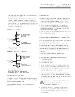
   Install the special 

installation tool

 (item 

#180212-095

) on 

the top of the shaft making sure it is tight to the flat base of 
the impeller to protect the seal from sharp edges during  
seal installation.

 12

   Apply a liberal amount  of non-petroleum based lubricant 

on the outside of the special plastic 

installation tool.


13

   Wipe any excess lubricant off of the stationary silicon  

carbide seal face with a lint free cloth and alcohol to ensure 
the surface is clean.

 14

  Install the new rotating seal element and spring assembly 

by gently pushing it (graphite ring first) over the 

installa-

tion tool

 and onto the shaft until the graphite ring presses 

tightly against the stationary seal seat. The seal spring may 
be compressed slightly.

15

   Remove the 

installation tool 

from the shaft.

16

  Install the impeller keeping the inlet end up. Make sure to 

align the flats to the shaft flats and push the impeller down 
tightly to the seal.

17

   Place 

2-3

 drops of medium strength thread locker liquid on 

the nut threads.

18

  Install the special left hand thread nut on the motor shaft. 

While holding the motor rotor in place as in step 

3

, thread  

the impeller nut on to the shaft in a counter-clockwise 
direction and tighten the nut to approximately 

6

ft-lbs.

 19

  If the impeller will not spin freely contact Armstrong  

Technical Support at 

1-416-755-2291

 or email  

[email protected]

20

  Ensure the gasket is properly seated in the pump casing 

(volute) gasket groove. Holding the motor body, insert 
the impeller straight into the volute. Verify the gasket was 
not dislodged during insertion, and is still seated properly. 
Hold the motor body steady while fastening the four bolts 
that attach the motor to the pump casing (volute). Tighten 
evenly and diagonally. There should be a small, even gap 
of about 

0.02

" (

0.5

 mm) between the motor flange and the 

pump casing (volute).

 21

   Follow the 

start up

 instructions (File no. 

10.84

)  

and check for leaks. 

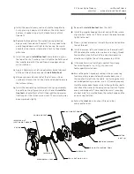
casing

impeller nut

(left hand thread)

mechanical seal

impeller

seal seat and l-cup

casing gasket

faceplate

housing extender

motor assembly

motor 

bolt (4)

seal installation tool

Summary of Contents for 182202-649

Page 1: ...te august 16 2012 Supersedes 10 84 Date july 20 2010 Kelly Walsh High School Tag PHX 1 Model E12 2 CI 120V Part 182212 841 Tag PHX 2 Model E17 2 CI 120V Part 182212 663 Tag PHX 3 Model E10 2 CI 120V T...

Page 2: ......

Page 3: ...ting limits 4 2 0 Electrical wiring 4 3 0 Start up 5 4 0 Preventive maintenance inspection 5 5 0 Pump replacement in an existing installation 5 5 1 Complete pump 5 5 2 Motor end only 6 6 0 Mechanical...

Page 4: ...rculator proper installation practice recommends a thorough flush of the hydronic system ensuring removal of all foreign materials warning Mount with motor shaft horizontal and terminal box above cent...

Page 5: ...glycol solution before starting 2 Air must be completely vented from the system before starting up the circulator If the system is not completely vented of air and the circulator is allowed to run dr...

Page 6: ...g careful of its attached impeller The motor is heavy do not drop it 8 Install new casing gasket 9 Install new motor end with impeller and seal kit 10 Tighten four motor end bolts in a crisscross patt...

Page 7: ...e seal spring may be compressed slightly 15 Remove the installation tool from the shaft 16 Install the impeller keeping the inlet end up Make sure to align the flats to the shaft flats and push the im...

Page 8: ...nited kingdom m11 2et 44 0 8444 145 145 93 east avenue north tonawanda new york u s a 14120 6594 1 716 693 8813 23 bertrand avenue toronto ontario canada m1l 2p3 1 416 755 2291 no 1619 hu hang road xi...

Page 9: ...BF Flange 116012 011 810120 210 P64230 2 105176 000 2 911123 114 2 913523 100 Flange kit N A H 51 BF Flange 116012 011 810120 218 N A 2 105176 001 4 911123 114 4 913523 100 Flange kit 816012 211 H 52...

Page 10: ...nge 116012 041 810120 210 P64230 2 105176 000 2 911123 114 2 913523 100 Flange kit N A H 51 AB Flange 116012 041 810120 218 N A 2 105176 001 4 911123 114 4 913523 100 Flange kit 816012 241 H 52 AB Fla...

Page 11: ...D 911125 118 hhcs 1 2 13 x 2 25 lcs 8 E16 E30 E33 911129 120 hhcs 5 8 11 x 2 1 2 lcs 8 913125 100 hh nut 1 2 13 lcs 8 913129 100 hh nut 5 8 11 unc 8 Part Description Qty Pump Model Part Description Qt...

Page 12: ...7 16 4 1 105188 011 105188 041 F74000 F74800 3 5 1 16 6 9 16 2 105189 011 105189 041 P03560 P06750 2 5 1 16 6 9 16 2 105210 011 105210 041 2 3 4 7 8 9 16 2 106073 011 106073 041 P01500 P06620 1 3 7 16...

Page 13: ......

Page 14: ......

Page 15: ......

Page 16: ......

Reviews: