ARJAY ENGINEERING 2852-DPM, User Manual
The ARJAY ENGINEERING 2852-DPM is a cutting-edge product designed to deliver exceptional performance. To ensure a seamless user experience, we provide a comprehensive User Manual that can be easily downloaded for free from our website. Gain valuable insights on operating and optimizing the product’s capabilities with our user-friendly manual.
Share
Download


Reviews:
No comments
Related manuals for 2852-DPM

300 Series
Brand: LaCie Pages: 15

AL1751
Brand: Acer Pages: 8

AL1717
Brand: Acer Pages: 2

AC501
Brand: Acer Pages: 13

AL2017
Brand: Acer Pages: 2

Awmidx ED322Q
Brand: Acer Pages: 2

AL722
Brand: Acer Pages: 8

AL513
Brand: Acer Pages: 40

G235H
Brand: Acer Pages: 4

B273H
Brand: Acer Pages: 2

B203HV
Brand: Acer Pages: 2

AL 1916W
Brand: Acer Pages: 2

AL506
Brand: Acer Pages: 9

AL1922 r
Brand: Acer Pages: 20

B203H
Brand: Acer Pages: 2

B193
Brand: Acer Pages: 3

AL1913
Brand: Acer Pages: 2
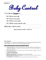
BC-200
Brand: Baby Control Digital Pages: 12


