background image

ARITERM SWEDEN AB


Installation, Operation & Maintenance - 

2009.02.18- 5/32

B 20/30 the new generation pellet boiler is equipped with a 20/30 kW built-

in pellet burner.  A pellet burner has many similarities with an oil burner. The dif-

ference is that heating with solid fuel produces ash that must be regularly removed to 

prevent loss of efficiency or impairment of burner performance. The boiler is designed 

to meet highest requirements as to operational reliability, convenience, and safety.

B 20/30 belongs to the most efficient state-of-the art pellet boilers in today’s 

marketplace. Optimal combustion efficiency and good insulation allows for a high 

coefficient of performance while emissions to the environment are kept at a low level. 

The boiler has automatic ignition but can always be ignited manually, if required. It 

has two ignition programs depending on whether the burner is started from the OFF 

position or from operating mode. Operation of the boiler and its feed system are fully 

automated and are regulated in three steps by the built-in control system. In the burn 

pot, pellets are mixed with air to the ideal proportion to ensure complete combustion 

in a cost effective manner. 

B 20/30 are equipped with an oversized  

ash box to facilitate maintenance work. Sweeping is mainly done from the soot-hatch 

on top of the boiler but also through the rebox door after the burner is pulled out. 

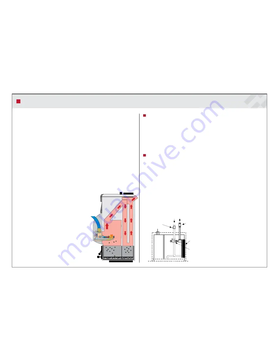
B 20/30 consists of a combustion  

chamber with flue pipes enclosed by a jacket  

holding 140/142 litres of water. Heat generated by  

the burner is transferred to the boiler water via  

the combustion chamber and the flue pipes.

Heat for the radiator system is transferred via a  

4-way shunt valve. In the shunt valve the boiler  

water is mixed with return water from the radiators  

so that a constant, correct temperature can be  

maintained in the radiators in relation to the outdoor  

temperature. This is a means to achieve better  

heating economy. 


Small dimensions for easy installation

Thanks to its modest dimensions B 20/30 can be installed in boiler rooms 

that would normally be considered too small. Most of the piping connections are 

placed on top of the boiler. The terminal block for electric installation is accessible 

from the control panel. Service work is facilitated by the fact that all connections and 

components are easily accessible from the front. Sweeping takes place through the 

rebox door or through a cleaning hatch on top of the boiler. Ashes collect in the oversi-

zed ash box that is attached to the ash door. The ash box holds 50 litre of ash and is 

emptied when necessary.


Hot tap water

The efficient plate heat exchanger will ensure that you always get “fresh” hot tap water. 

A strainer has been installed in the cold water line to prevent the heat exchanger from 

becoming clogged (the water quality should be checked).
The internal circulation pump is controlled by a flow switch, fitted on the hot water 

outlet pipe. The whole heat-exchanger package is located behind the electric panel and 

is easily accessible for service work.

ATTENTION!

 Before servicing, disconnect the power to the boiler by switching off the 

mains switches. Work on the boiler may only be carried out by a qualified electrician.

Front view of the heat exchanger 


installation for hot tap water.
1. Plate heat exchanger   


2. Internal circulation pump


OPERATING PRINCIPLE

The shunt valve can be regulated either manually or                                                                        

automatically with a regulating device (optional).

1

Flow switch

cw hw

Strainer

2

Summary of Contents for Biomatic plus 50

Page 1: ...ARITERM SWEDEN AB Installation Operation Maintenance 2009 02 18 1 32 INSTALLATION OPERATION AND MAINTENANCE Biomatic 20 Biomatic 30 ...

Page 2: ... cleaning to minimize the amount of glowing ash Warning Make sure to cut the power supply to the boiler before removing the burner housing Maintenance contract Ariterm recommends the boiler installation to be made by a company with professio nal competence For more information please contact your Ariterm retailer Replacing of spare parts Ariterm recommends that replacing of spare parts is made by ...

Page 3: ...Electrical data Power supply Supply cable Fuse size Power in operation 400 V 50 Hz MMJ 4x2 5s 3x16 A 9000 W Part Number Biomatic 20 part no 4010 Standard delivery Shunt valve ESBE TM 20 Sweeping gear Combination flue for horizontal and vertical installation part no 5206 Accessories Burner assembly kit Shunt outlet Biomatic 20 1 Drain DN 15 female 2 Flue pipe Ø 139 mm 3 Additional shunt optional 4 ...

Page 4: ...TECHNICAL DATA Performance Output using pellets Power of ignition resistor Normal power consumption 12 30 kW 450 W 70 W Dimensions Dimensions width x depth x height Weight Water contents Weight burner 606 x 970 x 1720 mm 330 kg 142 l 38 kg Design values Design pressure Design temperature Recommended draught 0 5 1 5 bar max 120 o C 5 20 Pa Connections Expansion Drain Flue pipe connection Recommende...

Page 5: ...r the radiator system is transferred via a 4 way shunt valve In the shunt valve the boiler water is mixed with return water from the radiators so that a constant correct temperature can be maintained in the radiators in relation to the outdoor temperature This is a means to achieve better heating economy Small dimensions for easy installation Thanks to its modest dimensions Biomatic 20 30 can be i...

Page 6: ...at outside the boiler wall which means that you do not have to rely on extra safety devices For details about the various alarm conditions please refer to Troubleshooting Safety is a natural part of the burner function Each time filling takes place only a limited amount of pellets 150 g is transported through the external feeding system from the storage bin to the top feed connection To make sure ...

Page 7: ...ntake must not be covered ATTENTION The chimneysweep must be notied for inspection of the flue CAUTION The boiler has low flue gas temperatures which under certain conditions might lead to condensation of flue gases INSTALLATION 30 Mortar Flue pipe 30 mm incom bustible insulation Imbedment into chimney A 1560 mm exkl ställbara fötter Golv Ø200 mm Water piping shall be carried out in accordance wit...

Page 8: ... floor heating 4 Circulation pump radiator heating 5 Floor heating distributor with choke valve and draught check plate 6 Radiator heating circuit 7 Expansion vessel 8 Service valve 9 Safety valve 10 Filler valve 11 Valve pipe with safety valve 12 Circulation pump for drain water 13 Expansion card 14 Outdoor temperature sensor 15 Flow water sensor 16 WATER PIPING 6 4 1 8 9 10 11 13 15 16 16 12 2 3...

Page 9: ...ork on the burner may only be carried out by a qualified serviceman Make sure to cut the power supply to the burner before servicing Before you begin heating the heating system must be filled with water To fill the system do as follows Open all shut off valves including the shunt valve The pump must be switched 1 off Fill the boiler and the radiator system with water Bleed the system at the radia ...

Page 10: ...ARITERM SWEDEN AB Installation Operation Maintenance 2009 02 18 10 32 WIRING DIAGRAM ...

Page 11: ...e for reminder alarm 3 Service Levels The control unit has different menu levels for the adjustment and viewing of the control system parameters The tables on page 14 17 will give you a detailed description of the menus shown on the control unit display panel Normally the control unit is at menu level 1 To reach menu level 2 Service do the following Press arrow forward and arrow backward at the sa...

Page 12: ... EL STEP 0 0 LEVEL MONITOR XX 50 OPTICAL MONITOR XX 50 TEST OUTPUTS Press plus key POWER 0 ENGLISH ADDRESS DEFAULT SETTINGS v0713 DIFF TANK NO AUGER EXTERNAL 0 FAN 0 AUGER BURNER 0 IGNITION 0 ALARM 0 EL STEP 0 Service meny shows when pushing same time buttoms and for 5 sec Power menu is available when nr 0 is changed to nr 5 Move forward when nr on display stops winking MAIN MENU SERVICE MENU POWE...

Page 13: ... the pellet fuel will ignite The boiler s optical monitor detects when the fuel has ignited and switches off the ignition element The red light goes out and the green comes on to confirm that the burner is operating Fan speed is reduced At the same time the fuel feed mo tor stops for three minutes to allow all the pellets in the burn pot to ignite After that pellets will be fed at reduced speed fo...

Page 14: ...er Operating time min Minimum power level during operating time only displayed when the min operating level is activated Operating time electric el1 Operating time of the resistor 1 The number of electric resistors vary bet ween models Operating time electric el2 Operating time of the resistor 2 The number of electric resistors vary bet ween models Pellet store press plus key Press the Plus button...

Page 15: ...g the Plus button Diff tank Hysteresis can be adjusted when using hot water supplier If diff tank setting is no holding time setting can also be no and the burner will always make cold start see also holding time No 1 60 C Activated by pressing the plus minus keys Description of menu 3 Power Power In order to activate this menu select number 5 in the Service Power menu by pres sing the Plus button...

Page 16: ...EL MONITOR XX 50 OPTICAL MONITOR XX 50 TEST OUTPUTS Press plus key POWER 0 ENGLISH ADDRESS DEFAULT SETTINGS v0906 DIFF TANK NO AUGER EXTERNAL 0 FAN 0 AUGER BURNER 0 IGNITION 0 ALARM 0 EL STEP 0 Service meny shows when pushing same time buttoms and for 5 sec Power menu is available when nr 0 is changed to nr 5 Move forward when nr on display stops winking MAIN MENU SERVICE MENU POWER MENU Menu is o...

Page 17: ... STEP 0 0 LEVEL MONITOR XX 50 OPTICAL MONITOR XX 50 TEST OUTPUTS Press plus key POWER 0 ENGLISH ADDRESS DEFAULT SETTINGS v0906 DIFF TANK NO AUGER EXTERNAL 0 FAN 0 AUGER BURNER 0 IGNITION 0 ALARM 0 EL STEP 0 Service meny shows when pushing same time buttoms and for 5 sec Power menu is available when nr 0 is changed to nr 5 Move forward when nr on display stops winking MAIN MENU SERVICE MENU POWER M...

Page 18: ...dy that the motor shaft rotates the auger and the motor of the external auger operates In most cases the default setting of the operating time of the external auger 30 seconds is not long enough to bring suf ficient amount of pellets to the burner If the problem cannot be removed by me ans of the above checks and remedies the operating time of the external auger may be too short In such cases incr...

Page 19: ...not detected light du ring a certain period of time No fuel has entered into the combus tion head is there fuel in the upper connection If there is no fuel in the upper con nection of the burner check the cable connections of the level switches If this does not help wipe the level swit ches clean If the external feed of the burner does not start in spite of this or the level switches must be clean...

Page 20: ...carbonisation Put the burner back into place check carefully that no sealing is damaged Once a year to once every second year Clean the primary ring and primary air tube on the inside to remove dust and chips Check the pins of the metering wheel the toothed wheel and the back stop for wear Adjust and replace if necessary Lubricate the driving chain with a little thin oil When new pellet fuel is us...

Page 21: ...r must not include anything but ash 9 Emptying the ash is even easier with an ash cyclone which works like a vacuum cleaner It is important not to vacuum hot ash because of the fire risk 11 Remaining ash which is collected in a fire proof container 12 can be used as a fertilizer 6 Remove the ash by brushing the walls of the combustion chamber Clean the burn pot and the air cracks 8 Ash compression...

Page 22: ...d materials for a period of 24 months 2 years from the date of installa tion The manufacturer shall not be held liable for faults caused by incorrect installa tion incorrect use freezing over temperature or over pressure Any attempts made to repair the product without the manufacturer s permission or if the guarantee card has not been returned to the manufacturer will invalidate the guarantee The ...

Page 23: ...safety grate and a cover NOTE Installation of PS300 Feedo see separate manuals for each product Depo The Depo discharge chute is a patented transport solution that efficiently functionally and at a low noise level feeds pellets from storage via a conveyor to the burner The Depo is particularly appropriate in combination with the Feedo screw conveyor Feedo The Feedo screw conveyor provides safe pro...

Page 24: ...ARITERM SWEDEN AB Installation Operation Maintenance 2009 02 18 24 32 FEEDING SYSTEM WEEKLY STORAGE 602 mm 1500 mm 606 mm 1208 mm 699 mm 606 mm 758 mm 920 mm 602 mm 602 mm ...

Page 25: ...ARITERM SWEDEN AB Installation Operation Maintenance 2009 02 18 25 32 FEEDING SYSTEM DEPO FEEDO 606 mm 1500 mm ...

Page 26: ...ARITERM SWEDEN AB Installation Operation Maintenance 2009 02 18 26 32 FEEDING SYSTEM DEPO FEEDO 606 mm 758 mm 920 mm ...

Page 27: ...ARITERM SWEDEN AB Installation Operation Maintenance 2009 02 18 27 32 MANUFACTURES DECLARATION ...

Page 28: ...ARITERM SWEDEN AB Installation Operation Maintenance 2009 02 18 28 32 NOTES ...

Page 29: ...ARITERM SWEDEN AB Installation Operation Maintenance 2009 02 18 29 32 NOTES ...

Page 30: ...ARITERM SWEDEN AB Installation Operation Maintenance 2009 02 18 30 32 NOTES ...

Page 31: ...temperature boiling risk If these instructions are not followed during installation operation and maintenance the obligations of Ariterm AB under the warranty regulations are no longer binding Ariterm reserves the right to alter any details and specifications without prior notice INSTALLATION PROTOCOL Flue gas temp High CO O2 CO2 Air fuel ratio Efficiency Draught i mm Fan Effect Flue gas temp Low ...

Page 32: ...ARITERM SWEDEN AB Installation Operation Maintenance 2009 02 18 32 32 Ariterm Sweden AB Flottilvägen 15 39241 Kalmar Sweden www ariterm se 46 480 442850 ...

Reviews: