13
5.2 P
OSITIONING
P
UMP
G
ROUP
F
IG
. 5.2
A
S
UGGESTED
L
OCATION
5.
INSTALLATION
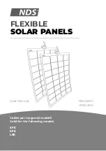
To Collector
Temperature
Sensor S1
From Collectors
To Collectors
AST 100
Controller
Cylinder
PRV
discharge
vessel
Fill point
Expansion
Vessel
Pump
Group
S3
S2
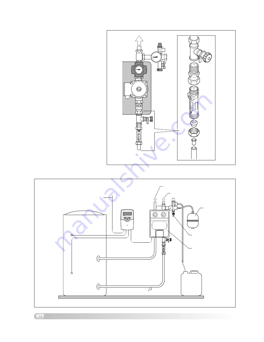
A flow limiter set is supplied separately, this must be fitted to the pump
group on the suction side of the pump as shown in fig. 5.1a.
F
IG
. 5.1
A
F
ITTING
F
LOW
L
IMITER
5.1 F
ITTING
F
LOW
L
IMITER
15Ø
Note:
The flow limiter is supplied with
fittings for 15Ø pipe.


