


22
Fig. 11.1
T
ERMINAL
P
OSITION
mm
A -
Directly above or below an openable window
or other opening
300
B -
Below gutters, solid pipes or drain pipes
75
C -
Below eaves
200
D -
Below balconies or car-port roof
200
E -
From vertical drain pipes and soil pipes
150
F -
From internal or external corners
300
G -
Above ground or balcony level
300
H -
From a surface facing a terminal
600
I -
From a terminal facing a terminal
1200
J -
From an opening in the car port
(e.g. door, window) into dwelling
1200
K -
Vertically from a terminal in the same wall
1500
L -
Horizontally from a terminal in the same wall
300
M -
Horizontally from an opening window
300
N -
Fixed by vertical flue terminal
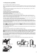
11. Connecting the Flue
The boiler should only be installed with a flue system supplied by MTS (GB) Limited.
These kits are supplied separately to the appliance in order to respond to different installation solutions. For more information
with regard to the inlet/outlet accessories consult the accessory catalogue. The boiler is supplied ready for connection to a
concentric flue system.
N
OTE
: S
EE PAGE
28
FOR MAXIMUM AND MINIMUM FLUE RUNS
(T
ABLES
A, B
AND
C)
Warning
The exhaust gas ducts must not be in contact with or close to inflammable
material and must not pass through building structures or walls made of
inflammable material.
When replacing an old appliance, the flue system must be changed.
Important
Ensure that the flue is not blocked.
Ensure that the flue is supported and
assembled in accordance with these
instructions.
I
MPORTANT
!!
BEFORE CONNECTING THE FLUE
,
ENSURE THAT
1/4
LITRE OF
WATER HAS BEEN POURED INTO THE EXHAUST CONNECTION
TO FILL THE CONDENSATE TRAP
.
SHOULD THE TRAP BE
EMPTY THERE IS A TEMPORARY RISK OF FLUE GASSES
ESCAPING INTO THE ROOM
.
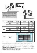
150 mm
* pente 5 mm par mètre
150 mm
* pente
Installation without extension
Installation with extension
Level
slope 5 mm per metre
slope


