5
installation
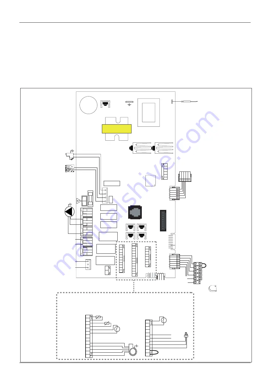
Electrical diagram
For increased safety, ask a qualified technician to perform a
thorough check of the electrical system.
The manufacturer is not responsible for any damage caused by
the lack of a suitable earthing system or by the malfunctioning of
the electricity mains supply.
ROOM
FLOOR
OTS
CN1
CN16
CN21
DISPLA
Y
CN2
CN25
FLOW
CN1
4
TIMER
CN15
FAN
PUMP + SPEED
DIVERTR
VAL
VE
ZONE + FILLING
FET5
FET1
FET4
FET3
FET2
CN11
FAST
FUSE 2A
1
8
REMOTE CONTROL
CN2
4
CN6
FLAME
CN
5
EAR
TH
C
N
19
1
2
3
4
CN3
N
L
CN2
0
FILLING EXT
. P
.
1
2
3
4
CN1
2
FA
N
P
UM
P
PUMP
SPEED
1
2
3
4
5
6
CN1
0
DIVE
R
TER
VA
LV
E
CN9
6
5
4
3
2
1
EPROM KE
Y
C
N
18
8
7
6
5
4
3
2
1
CN7
12
13
11
10
9
8
7
6
5
4
3
2
1
CN22
11
10
9
8
7
6
5
4
3
2
1
CN
4
2
1
CN17
Electrod
e
ionisatio
n
5
1
Af
fichage
Thermostat dʼambianc
e
Thermostat plancher chauf
fant
Sonde extérieure
6
1
Allumeur
Va
nn
e
Gaz
Circulateu
r
Electrovanne remplissag
e
Va
nn
e
distributrice
Débistat sanitaire
Sonde sanitair
e
P
Sonde pression circuit primair
e
Sécurité
surchauf
fe
11
10
9
8
7
6
5
4
3
2
1
CN
4
Ve
ntilateu
r
Thermofusibl
e
échangeur
12
13
11
10
9
8
7
6
5
4
3
2
1
CN2
2
Sonde retour circuit primaire
Sonde dépar
t
circuit primair
e
ig
nit
or
det
ec
tion
elec
tr
ode
gas
valv
e
displa
y
room
ther
mosta
t
under
floor
hea
ting
ex
ter
nal
sensor
cir
cula
tion
pump
C.H. flo
w
temp
. pr
obe
ther
mal fuse
modula
ting
fan
ov
er
hea
t
ther
mosta
t
C.H. r
etur
n
temp
. pr
obe
swit
ch On-
O
ff


