background image

-- 51 --

bu09d12e2

7

MAINTENANCE

Note:

All warranty undertakings given by the supplier cease to apply if the customer

attempts to rectify any faults on the machine during the warranty period.

Only those persons who have appropriate electrical knowledge (authorised

personnel) may remove the safety plates to connect or carry out service,

maintenance or repair work on welding equipment.

Cleaning

Check regularly that the power source is free from dirt.

How often, and to what extent, cleaning should be carried out depends on the

welding process, arc time, disposition and the surrounding environment. It will

normally suffice to blow the power source clean using compressed air (reduced

pressure) once a year.

If the power source is very dirty, brushing and vacuuming are recommended.

S

Disconnect the welding power source from the mains current supply.

S

Remove the adapter from the socket. Lock the socket to prevent unauthorised

connection.
At fixed installations, the safety switch should be set to the off position. Lock

the switch.

S

Remove the power source’s safety plates for best access.

After cleaning, all safety plates must be mounted before you connect the power

source to the mains supply.

7.1

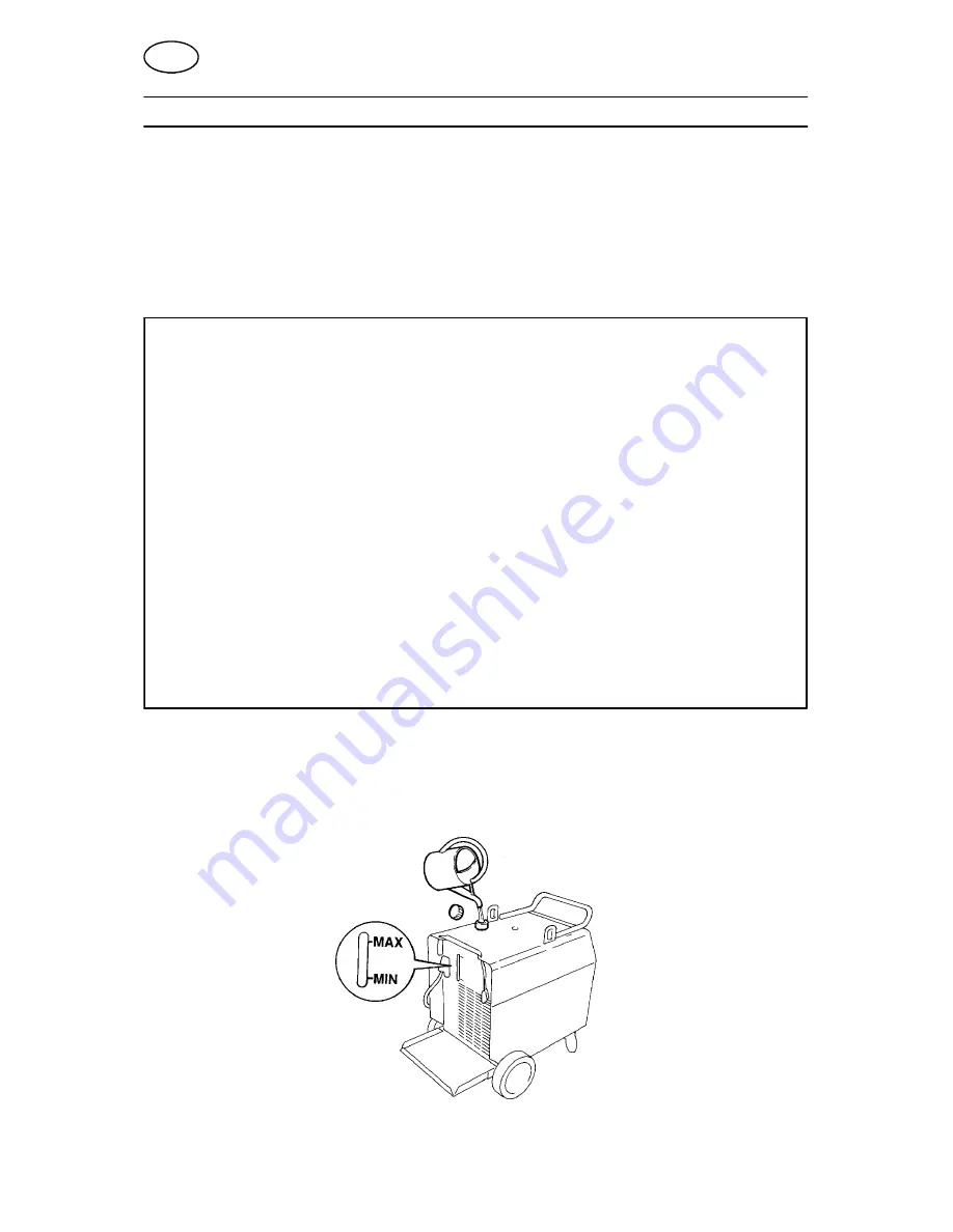
Topping up coolant

We recommend a 50/50 % mixture of water and ethylene glycol.

GB

Summary of Contents for 320

Page 1: ...6 Aristo 320 Aristo 450 LUD 320 LUD 450 Bruksanvisning Brugsanvisning Bruksanvisning Käyttöohjeet Instruction manual Betriebsanweisung Manuel d instructions Gebruiksaanwijzing Instrucciones de uso Istruzioni per l uso Manual de instruções Ïäçãßåò ñÞóåùò ...

Page 2: ... modifications sans avis préalable Recht op wijzigingen zonder voorafgaande mededeling voorbehouden Reservado el derecho de cambiar las especificaciones sin previo aviso Ci riserviamo il diritto di variare le specifiche senza preavviso Reservamo nos o direito de alterar as especificações sem aviso prévio Äéáôçñåßôáé ôï äéêáßùìá ôñïðïðïßçóçò ðñïäéáãñáöþí ùñßò ðñïåéäïðïßçóç SVENSKA 3 DANSK 13 NORSK ...

Page 3: ...ting control 45 4 TECHNICAL DATA 45 5 INSTALLATION 46 5 1 MAINS SUPPLY 48 5 2 Termination resistance 48 5 3 Electrical installation 49 6 OPERATION 50 7 MAINTENANCE 51 7 1 Topping up coolant 51 8 ORDERING OF SPARE PARTS 52 DIAGRAM 124 SPARE PARTS LIST 127 ACCESSORIES 142 ...

Page 4: ...ll S Install and earth the welding unit in accordance with applicable standards S Do not touch live electrical parts or electrodes with bare skin wet gloves or wet clothing S Insulate yourself from earth and the workpiece S Ensure your working stance is safe FUMES AND GASES Can be dangerous to health S Keep your head out of the fumes S Use ventilation extraction at the arc or both to take fumes an...

Page 5: ...ee the programming manual 456 685 xxx 4 TECHNICAL DATA LUD 320 320 W LUD 320 320 W Voltage 400V 3 50 60 Hz 230 400 500V 3 50Hz 208 230 460 475V 3 60 Hz Permissible load at 100 duty cycle 60 duty cycle 270A 30 8V 320A 32 8V 270A 30 8V 320A 32 8V Setting range MIG MAG 15A 15V 8V 320A 30V 30A 15V 8V 320A 30V Setting range MMA 16A 20V 320A 32 8V 10A 20V 320A 32 8V Setting range TIG 4A 10V 320A 22 7V 1...

Page 6: ...IP 23 IP 23 Weight kg 96 110 143 157 Dimensions lxwxh 910x642x835 910x642x835 Application classification These welding rectifier conform to the requirements of IEC 974 1 Duty cycle The duty cycle refers to the time as a percentage of a ten minute period that you can weld at a cer tain load without overloading the welding power source Enclosure class The IP code indicates the enclosure class i e th...

Page 7: ...g it along the ground Lifting instructions IMPORTANT S Place the welding power source in a suitable place and make sure the welding rectifier is not covered or set up so that cooling is prevented S Make sure the welding rectifier is connected to the correct mains voltage Earth according to applicable directives GB ...

Page 8: ...0 24 5 18 5 45 41 20 19 5 60 51 30 5 23 57 5 51 5 25 24 5 45 55 5 34 25 62 56 5 27 5 26 5 Mains lead rating 4x10 4x4 4x4 4x10 4x10 4x4 4x4 Fuse slow A 50 20 20 50 50 20 20 5 2 Termination resistance The termination resistance must be connected to the ends of the CAN bus to prevent communication problems The controller has a built in terminator but the power source and wire feed unit do not The ter...

Page 9: ... 49 bu09d12e2 5 3 Electrical installation 400 V 3 50 60 Hz 208 V 60Hz 230 V 50 60 Hz LUD 320 320W 4x10 mm LUD 450 450W 4x10 mm GB ...

Page 10: ...al connector TIG OKC connector MMA MIG MAG A Power on off B Cooling unit on off LUD 320W 450W C Power on light D Thermal cut out warning light lights up in case of overheating E Welding terminal polarity F Welding terminal polarity G Welding terminal polarity H Automatic fuse 42 V AC circuit I Central connector TIG torch polarity HF J Water connection TIG torch K OKC connector TIG torch polarity H...

Page 11: ...ess arc time disposition and the surrounding environment It will normally suffice to blow the power source clean using compressed air reduced pressure once a year If the power source is very dirty brushing and vacuuming are recommended S Disconnect the welding power source from the mains current supply S Remove the adapter from the socket Lock the socket to prevent unauthorised connection At fixed...

Page 12: ...re feed cabinet using the straps supplied When moving the equipment do NOT pull on the torch WARNING 8 ORDERING OF SPARE PARTS Spare parts are ordered through your nearest ESAB representative see back cover When ordering spare parts please state machine type and number as well as desig nation and spare part number as shown in the spare parts list This will simplify dispatch and ensure you get the ...

Reviews: