Arista 7500N Series Quick Start Manual Download Page 59

Appendix B: Parts List

Four Post Rack Mount for 12-slot and 16-slot Chassis

Quick Start Guide: 7500N Series Modular Switches

53

B.4

Four Post Rack Mount for 12-slot and 16-slot Chassis

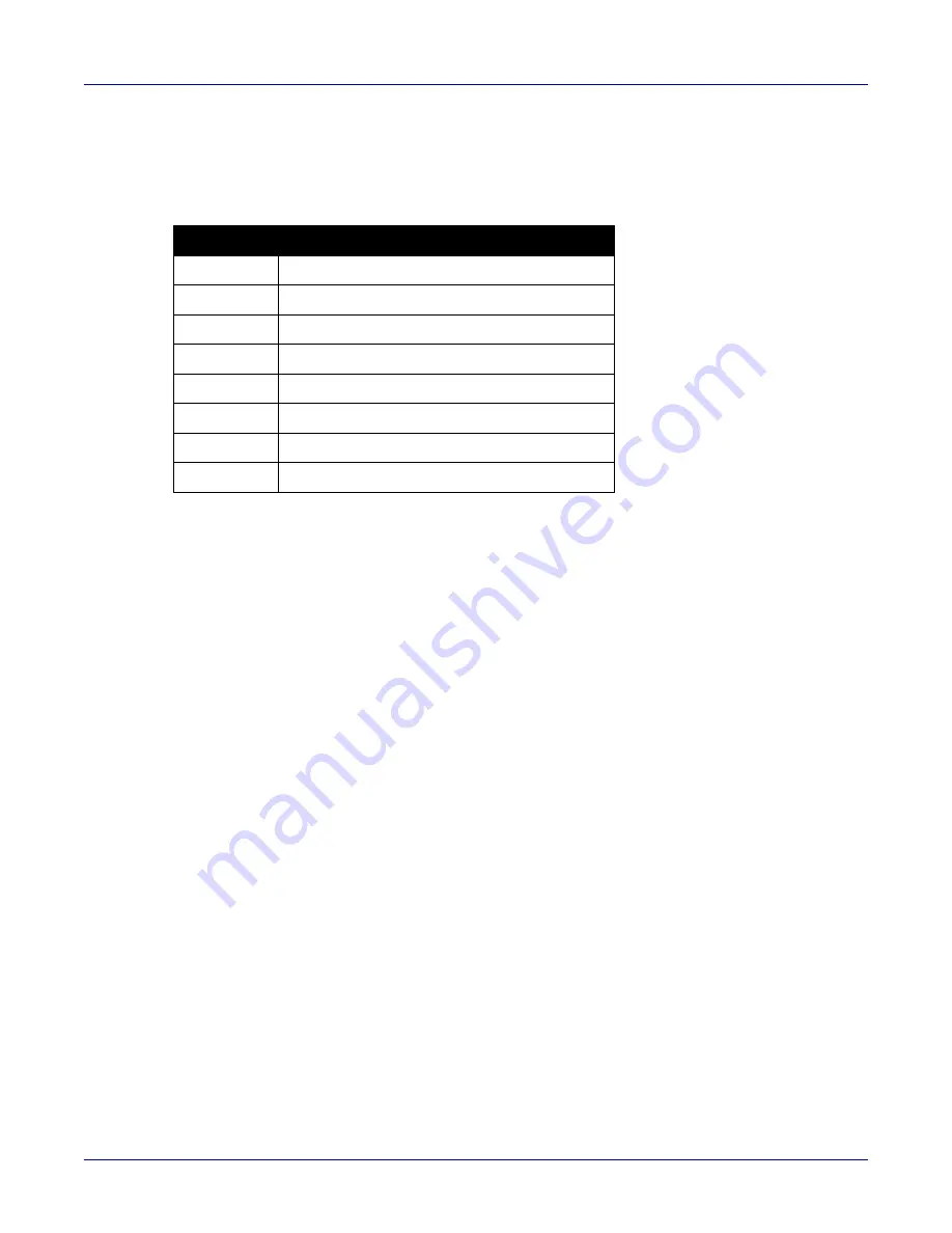
The following sections list the parts provided in the accessory kit for four-post rack mount installations 
of the 12- and 16-slot chassis.

Table B-5  Four-Post rack mount parts for the 12- and 16-slot chassis

Quantity

Description

1

Shelf (or cradle)

1

Left shelf support

1

Right shelf support

25

M6 cage nuts square hole

25

M6X16 pan-head Phillips screws

25

M5X16mm pan-head Phillip screws

25

12-24X5/8 pan-head Phillip screws

27

10-32X5/8 pan-head Phillip screws

Summary of Contents for 7500N Series

Page 1: ...Quick Start Guide 7500N Series Modular Data Center Switch Arista Networks www arista com PDOC 00114 14 ...

Page 2: ...ks and the Arista logo are trademarks of Arista Networks Inc in the United States and other countries Other product or service names may be trademarks or service marks of others Headquarters 5453 Great America Parkway Santa Clara CA 95054 USA 1 408 547 5500 www arista com Support 1 408 547 5502 1 866 476 0000 support arista com Sales 1 408 547 5501 1 866 497 0000 sales arista com ...

Page 3: ... 3 1 1 Two Post Rack Mount 11 3 1 2 Attaching Mounting Brackets to the Chassis 11 3 1 3 Inserting the Switch into the Rack 12 3 1 4 Four Post Rack Mount 13 3 1 5 Assembling the Shelf 13 3 1 6 Inserting the Switch into the Rack 16 3 2 7512N and 7516N Shelf Rack Mount Installation 17 3 2 1 Assembling the Shelf 17 3 2 2 Inserting the Switch into the Rack 22 Chapter 4 Cabling the Modular Switch 25 4 1...

Page 4: ... Status Indicators 44 A 4 Power Supply Status Indicators 45 Appendix B Parts List 49 B 1 Parts Used in All Rack Mount Configurations 50 B 1 1 Cables 50 B 1 2 Getting Started Booklet 50 B 2 Two Post Rack Mount Parts 50 B 3 Four Post Rack Mount Parts for 4 slot and 8 slot Chassis 51 B 4 Four Post Rack Mount for 12 slot and 16 slot Chassis 53 Appendix C Front Panel 55 Appendix D Rear Panel 59 Appendi...

Page 5: ...ng the Touch Point Shield 77 F 4 Supervisor Module 78 F 4 1 Removing Supervisor Module 78 F 4 2 Removing Supervisor Module Blank 78 F 4 3 Installing Supervisor Module 78 F 5 Linecards 78 F 5 1 Removing Linecard 79 F 5 2 Removing Linecard Blank 79 F 5 3 Installing Linecard 79 Appendix G Taiwan RoHS Information 81 ...

Page 6: ...vi 9 March 2020Quick Start Guide 7500N Series Modular Switches ...

Page 7: ...ged the carrier may need to inspect them If the boxes were not damaged in transit unpack them carefully Ensure that you do not discard any accessories that may be packaged in the same box as the main unit Inspect the packing list and confirm that you received all listed items Compare the packing list with your purchase 7500N Series Modular Switches order Appendix B provides a list of components in...

Page 8: ...aux 21 CFR 1040 ne soit pas dépassée après avoir installé l émetteur récepteur de laser Ne pas installer des appareils à laser dont la cote de classe est supérieure à 1 Voir toutes les consignes de sécurité qui ont accompagné l émetteur récepteur avant l installation Seuls appareils laser de classe 1 certifiés pour une utilisation dans le pays d installation par l organisme compétent doivent être ...

Page 9: ...per circuit 48 60 V DC 48 60 V DC 48 60 V DC 48 60 V DC DC Branch Circuit Protection 100 A 100 A 100 A 100 A AC Input Voltage per circuit 200 240 V 200 240 V 200 240 V 200 240 V AC Branch Circuit Protection 20 A 20 A 20 A 20 A Input Power Circuits 2 to 4 circuits 2 to 8 circuits 2 to 12 circuits 6 to 20 circuits Ambient Temperature Storage Temperature Relative Humidity Altitude 0 to 40 C 32 to 104...

Page 10: ... LC DCS 7500R3 36CQ LC DCS 7500R3K 36CQ LC DCS 7500R3 24P LC DCS 7500R3 24D LC 450 W 556 W 212 W 305 W 197 W 285 W 408 W 495 W 300 W 320 W 414 W 486 W 318 W 332 W 758 W 863W 368 W 406 W 202 W 220 W 944 W 1040 W 313 W 350 W 601 W 654 W 830 W 921 W 845 W 941 W 963 W 1085 W 830 W 921 W 253 W 276 W 900 W 1180 W 410 W 450 W 410 W 450 W 538 W 558 W 530 W 550 W Fabric Modules DCS 7504E FM DCS 7508E FM DC...

Page 11: ...9100 W 10300 W 11000 W Full Chassis loaded with 2 DCS 7500 SUP2 6 DCS 7508R FM 8 DCS 7500R2 36CQ LC 6400 W 7300 W 7900 W 7512N Series System Note 7512N systems support only 7500R and 7500R3 Series Line cards Full chassis loaded with 2 DCS 7500 SUP2 6 DCS75012R FM 12 DCS 7500R 36CQ LC 12800 W 14700 W 15300 W Full Chassis loaded with 2 DCS 7500 SUP2 6 DCS 7512R FM 9 DCS 7500R 36CQ LC 3 DCS 7500R 36Q...

Page 12: ...se Temp Elevation 7516N Series System Note 7516N systems support only 7500R Series Line cards Full chassis loaded with 2 DCS 7516 SUP 6 DCS7516R FM 16 DCS 7500R 36CQ LC 16 PWR 3KT AC RED 16000 W 19000 W 21000 W Full chassis loaded with 2 DCS 7516 SUP 6 DCS7516R FM 16 DCS 7500R2 36CQ LC 16 PWR 3KT AC RED 13500 W 15600 W 17500 W Full chassis loaded with 2 DCS 7516 SUP 6 DCS7516R FM 16 DCS 7500RM 36C...

Page 13: ...ensions and footprint of the switch clearance requirements for the switches Figure 2 1 Clearance requirements and footprint for switches Table 2 1 shows the dimensions for each of the modular switches Table 2 1 Clearance requirements and footprint dimensions Switch Clearance Requirements Dimensions A B C DCS 7504N 60 cm 24 in 88 6 cm 34 9 in 36 8 cm 14 5 in DCS 7508N 60 cm 24 in 88 6 cm 34 9 in 36...

Page 14: ...ons for more details regarding your switch Important DC cables should be protected with circuit over current protection devices and circuit disconnect means To power off a unit power must be disconnected from ALL power cables DC câbles doivent être protégés avec dispositifs de protection de surintensité circuit et moyens de déconnexion du circuit Pour alimenter un appareil hors tension l alimentat...

Page 15: ...ESD damage when installing or servicing the switch Assemble or disassemble equipment only in a static free work area Use a conductive work surfaces such as an anti static mat to dissipate static charge Wear an ESD wrist strap to dissipate static charge accumulation Minimize handling of assemblies and components Keep replacement parts in their original static free packaging Remove all plastic foam ...

Page 16: ...10 Quick Start Guide 7500N Series Modular Switches Electrostatic Discharge ESD Precautions Chapter 2 Preparation ...

Page 17: ...he four post rack Illustrations in this chapter depict the mounting of an unpopulated 12 slot chassis and a 16 slot chassis After completing the instructions for your rack type proceed to Chapter 4 3 1 7504N and 7508N Rack Mounting 3 1 1 Two Post Rack Mount To mount the switch to a two post rack assemble mounting brackets to the middle of the chassis then attach the brackets to the rack The switch...

Page 18: ...o the Rack Step 1 Move the chassis to the rack using a mechanical lift If modules are inserted in the chassis use the lift carefully to avoid damaging any components Step 2 Lift the chassis into the rack Position the flanges against the rack posts Figure 3 2 Figure 3 2 Lifting the chassis into the two post rack Step 3 Select mounting screws that fit your equipment rack 1 Center mount brackets ...

Page 19: ...cing the switch on the shelf Illustrations in this chapter depict the mounting of an unpopulated 8 slot chassis The accessory kit provides the following four post mounting parts 2 front brackets 4 shelf supports 2 back brackets not needed for racks with threaded holes left shelf right shelf Figure 3 4 on page 14 displays the front four post mounting parts Figure 3 5 on page 15 displays the rear fo...

Page 20: ...tep 4 Attach the shelf support and back bracket to the left rear post Figure 3 5 left The shelf support must be assembled at the same vertical level on the front and rear posts An up arrow is printed on the shelf support to indicate its proper orientation Unthreaded rack holes Attach the parts as displayed in Figure 3 5 left Threaded rack holes Attach the shelf support to the post with screws that...

Page 21: ...nd step 4 Align the holes and hook with the stubs on the brackets as shown in Figure 3 7 Lower the shelf such that the bracket stubs are inserted into the shelf holes and hook Step 7 Press down firmly on the shelf to ensure it is seated securely on the rack posts Step 8 Install the right shelf on the right front and right rear rack posts by repeating step 5 and step 6 to obtain the rack configurat...

Page 22: ...identical for the 7504N and 7508N switches Illustrations in this chapter depict the mounting of an unpopulated 8 slot chassis Step 1 Move the chassis to the rack using a mechanical lift Figure 3 8 Note If modules are inserted in the chassis use the lift carefully to avoid damaging any components Step 2 Lift the chassis into the rack Figure 3 8 Lifting the chassis 1 Left shelf 3 Right shelf 2 Rear ...

Page 23: ...posts Figure 3 9 Figure 3 9 Secure the switch to the rack shelf Step 4 After completing the Four Post Installation proceed to Chapter 4 3 2 7512N and 7516N Shelf Rack Mount Installation The rack mounting assembly is for the 7512N and 7516N Series switch 3 2 1 Assembling the Shelf Step 1 For threaded racks remove the plastic alignment spacers and use the 3 mm diameter alignment pins Figure 3 10 Fig...

Page 24: ...odular Switches 7512N and 7516N Shelf Rack Mount Installation Chapter 3 Rack Mounting the Switch Figure 3 11 Rack mount shelf orientation 1 7512N Top Front 4 Cage nut locations 2 7516N Top Front 5 Switch Bottom 3 Rack Rear both switches ...

Page 25: ...it Threaded rack holes Attach the front bracket to the post with screws that can be threaded through the rack post Step 3 Hook the alignment pin to the bottom hole of the 6th U from bottom Figure 3 12 on page 20 Table 3 1 Cage nut locations on rack Switch Cage Nut Locations 7512N Front of the rack Top hole 1st U Middle hole 2nd U Middle hole 4th U Bottom hole 5th U Top hole 9th U Middle hole 15th ...

Page 26: ...ft rear post Figure 3 13 on page 21 The shelf support must be assembled at the same vertical level on the front and rear posts An up arrow is printed on the shelf support to indicate its proper orientation Unthreaded rack holes Use the M6 screws and cage nuts supplied in the accessory kit Threaded rack holes Attach the shelf support to the post with screws that thread into the rack post 1 For thre...

Page 27: ...e the shelf supports installed on the left and right rack posts step 2 and step 3 Align the holes and hook with the stubs on the brackets Lower the shelf such that the shelf support bracket stubs are inserted into the shelf holes and hook Figure 3 14 on page 22 Step 7 Rear Fasten screws to all holes Front Fasten screws only where indicated with arrows 2x Rear Fasten screws to all holes 1 Install a...

Page 28: ... is seated securely on the rack posts 3 2 2 Inserting the Switch into the Rack The rack mounting assembly is identical for all 7500N Series switches Illustrations in this chapter depict the mounting of an unpopulated 12 or 16 slot chassis Step 1 Move the chassis to the rack using a mechanical lift Figure 3 15 on page 23 shows the 12 slot If modules are inserted in the chassis use the lift carefull...

Page 29: ... 7512N and 7516N Shelf Rack Mount Installation Quick Start Guide 7500N Series Modular Switches 23 Figure 3 15 Lifting the 12 slot chassis Step 2 Carefully install the switch into the rack Figure 3 16 Installing the switch into the rack ...

Page 30: ...ing the Switch Figure 3 17 Secure the chassis to the rack Step 3 Ensure the rack kit is firmly installed Step 4 Secure the chassis by use of 10 rack screws attaching the ears of the chassis to the front flanges of the rack posts Figure 3 17 Step 5 After completing the Shelf Rack Mount Installation proceed to Chapter 4 ...

Page 31: ...ementation appropriés et des autorités de contrôle pour assurer la conformité Note Many configurations will require additional power supplies Nombreuses configurations exigera des alimentations supplémentaires Important All power supply slots must be filled with either a power supply or blank to ensure proper air flow Tous les emplacements d approvisionnement de puissance doivent être remplis avec...

Page 32: ...oints Important Grounding wires and grounding lugs are not supplied Wire size should meet local and national installation requirements Commercially available 2 or 4 AWG wire is recommended for installations in the U S À la terre et de mise à la terre fils cosses ne sont pas fournis Calibre des fils doit satisfaire des exigences de l installation locale et nationale Disponible dans le commerce 2 ou...

Page 33: ...e length Le 48V et câbles de batterie retour sont une paire courir à côté de l autre et doivent être à peu près la même longueur 4 4 1 DC Power Supplies The 7500N Series chassis supports two DC power supplies PWR 3K DC RED Power Supply DC Power Adapter Installation for PWR 2700 DC R 4 4 2 Wire and Lug Preparation Before performing any installation actions ensure power is removed from DC circuits b...

Page 34: ...5 8 centers The PWR 2700W DC R ground lug is a right angle lug Check the terminations for the appropriate wire size Use a ground wire of at least 2 4 AWG Use only copper wire Step 3 Slip on heat shrink tubing on the wire ends before assembling the lugs on to the wire The lugs must be crimped with the proper tool The tubing should extend over the lug s barrel and the wire s insulator Step 4 Shrink ...

Page 35: ...WR 2700 DC R 4 5 1 Connecting the Power Cable Lug to the Terminal Studs Step 1 Prepare the stranded wiring see Section 4 4 2 Step 2 Remove the clear plastic cover protecting the terminal studs on the adapter by lifting the small center tab while sliding the cover off the adapter 4 5 2 Connecting the Ground to PWR 2700 DC R Power Supply The primary ground on the system requires a 2 4 AWG 5 16 inch ...

Page 36: ...tion 4 4 2 Step 2 Attach the ground cable to the ground stud Step 3 Tightening Torque 2 7 N m 24 in lbs 4 5 3 Connecting the Power Cable Lug to the Terminal Studs Step 1 Prepare the stranded wiring see Section 4 4 2 Step 2 Remove the clear plastic cover protecting the terminal studs on the adapter by lifting the small center tab while sliding the cover off the adapter 1 Ground 1 Plastic lid 2 Cent...

Page 37: ...h of the terminal studs Step 4 Secure each power cable lug to the terminal studs with the flange locking nuts Attach the positive DC source power cable lug to the RTN return terminal Attach the negative DC source power cable lug to the 48V input terminal Torque the four flange locking nuts to 2 7 N m 24 in lbs 1 Flange locking nuts 1 Compression lugs 3 48V 2 Compression lugs 4 RTN ...

Page 38: ... power supply Step 7 Tighten the two captive screws on the bottom of the adapter to the power supply module Torque screws with 2 Posidriv to 2 N m 17 7 in lbs Step 8 Attach the power cable to the DC power source Important Apply the ground connection first during installation and remove last when removing power Appliquer le motif connexion tout d abord pendant l installation et supprimer dernière l...

Page 39: ...equire the minimum number of PSUs as specified in Table 4 2 in the top section behind the supervisors For 8 12 slot chassis grouped power supplies top and bottom Arista recommends equal number of power supplies in the top and bottom groups For the 16 slot chassis with 2 power domains the power domain with the lowest number of power supplies prescribes the total power available therefore Arista rec...

Page 40: ... wire ABAB left to right All power supply slots must be filled with a powered supply A or B or a blank X or a non powered power supply For supervisor cooling purposes all systems require a minimum number of operating power supplies see Table 4 2 at all times in the top half of the chassis For optimal performance alternate pairs of power supplies A and B evenly from top to bottom 8 or more slot cha...

Page 41: ...isés doivent être occupés ou recouvert d un blanc pour assurer la bonne circulation d air dans le châssis 4 9 Connecting Supervisor Cables Supervisor modules contain console management and USB ports Figure 4 6 and Figure 4 7 displays port locations on the supervisors Refer to the chassis specification in Table 4 3 for additional information Figure 4 6 Supervisor DCS 7500E SUP 1 Status LED 5 Fan mo...

Page 42: ...CS 7516 SUP supervisor cards must be installed in one of the two slots designated for them in the DCS 7516N switch as shown in Figure 4 9 1 Status LED 5 Clock input port optional 9 Power supply status LED 2 USB ports 6 Fan module status LED 10 Active LED 3 Ethernet management ports 7 Fabric module status LED 4 Serial console port 8 Linecard status LED 1 Status LED 5 Clock input port optional 9 Pow...

Page 43: ...rds are numbered 3 through 18 Figure 4 9 DCS 7516N Supervisor Slots Table 4 3 RJ 45 to DB 9 Connections Ethernet management port Connect to 10 100 1000 management network with RJ 45 cable USB Port May be used for software or configuration updates Clock Input Port Port type is MCX connector 2 5 5V 50 ohm termination 1 Supervisor slot 1 2 Supervisor slot 2 RJ 45 DB 9 RJ 45 DB 9 RTS 1 8 CTS GND 5 5 G...

Page 44: ...as required to line card module ports or fixed MPO ports Supervisor and line card module ejectors on the front of the chassis assist with cable management Caution Excessive bending can damage interface cables especially optical cables Flexion excessive peut endommager les câbles d interface en particulier les câbles optiques Note You must ensure that any open slots for modules power supplies etc a...

Page 45: ...ines a default route to a network gateway Step 1 Provide power to the switch Chapter 4 Step 2 Connect the console port to a PC As the switch boots without a startup config file it displays this message through the console The device is in Zero Touch Provisioning mode and is attempting to download the startup config from a remote system The device will not be fully functional until either a valid s...

Page 46: ...ess 192 0 2 8 24 in this example to an Ethernet management port localhost config interface management 1 1 localhost config if Ma1 1 ip address 192 0 2 8 24 Step 10 Save the configuration by typing write memory or copy running config startup config localhost copy running config startup config Step 11 When the management port IP address is configured use this command to access the switch from a host...

Page 47: ...ndicators 7500E SUP 7500 SUP2 The supervisor provides one serial console port two Ethernet management ports two USB ports and one clock input port Supervisor activity is reported by LEDs in the upper left corner Four LEDs located left of the input ports report status of other switch components Figure A 1 Supervisor 7500E SUP 1 Status LED 5 Fan module status LED 9 Active LED 2 USB ports 6 Fabric mo...

Page 48: ...l 9 Power supply status LED 2 USB ports 6 Fan module status LED 10 Active LED 3 Ethernet management ports 7 Fabric module status LED 4 Serial console port 8 Linecard status LED 1 Status LED 5 Clock input port optional 9 Power supply status LED 2 USB ports 6 Fan module status LED 10 Active LED 3 Ethernet management ports 7 Fabric module status LED 4 Serial console port 8 Linecard status LED Table A...

Page 49: ...card module provides one status LED plus LEDs for each port on the card The figures in Appendix E indicate the location of the LEDs on each line card Figure A 4 Line card Status LED Active Off Not active Green Active and controlling the switch Table A 2 Component activity LED states LED Name LED State Module State Power Supply Line Card Fabric Module Fans Off No modules are present or powered Gree...

Page 50: ... interprets the port LED states A 3 Fabric Status Indicators Fabric Status LEDs are on fan fabric modules Appendix D displays the position of these LEDs on the rear of each switch Figure A 5 on page 44 displays fan status and fabric status LEDs on the switch Note Gen 1 Fabric modules are not supported Figure A 5 7504N left and 7508N fan status and fabric status LEDs Table A 3 Line card status LED ...

Page 51: ...R 2700 DC R PWR 3K DC RED The power supply LEDs are on the power supply modules The position of the LEDs are on the rear of each switch Figure A 7 on page 46 displays all the power supply modules supported on the 7500N 1 Fan status LED 3 Fabric status LED 2 Fabric status LED 4 Fan status LED 1 Fabric status LED 2 Fan status LED Table A 5 Fan status and fabric status LEDs on rear panel LED State St...

Page 52: ...lar Switches Power Supply Status Indicators Appendix A Status Indicators Figure A 7 7500N power supplies Note The LEDs for the power supplies with three LED status indicators are DC Good Fault and Vin Good from top to bottom as shown above ...

Page 53: ...ood Fault Vin Good Green Off Green Green Off Green Green Input power present Main output off DC Good Fault Vin Good Off Off Green Off Off Green Blinking Green Input power present Power Supply Fault DC Good Fault Vin Good Off Blinking Amber Green Off Blinking Amber Green Blinking Amber 1 sec on 1 sec off No Input Power Supply installed in chassis DC Good Fault Vin Good Off Off Off Off Off Off Off I...

Page 54: ...48 Quick Start Guide 7500N Series Modular Switches Power Supply Status Indicators Appendix A Status Indicators ...

Page 55: ...use only with Arista products Câbles d alimentation doivent être utilisés uniquement avec des produits de Arista Table B 1 Accessory kits for the modular switches 7504N 7508N 7512N 7516N Common cables and accessories See Section B 1 Included Included Included Included Two Post rack mount parts See Section B 2 Included Included N A N A Four post rack mount kit for 4 slot and 8 slot chassis See Sect...

Page 56: ... sections list the parts provided for the two post rack mount installation Figure B 1 Two Post rack mount parts Table B 2 Cables Provided in Accessory Kit Quantity Description 2 RJ 45 Patch Panel Cables 2 meters 2 RJ 45 to DB9 Adapter Cable 2 meters Table B 3 Two Post rack mount parts Quantity Description 2 Center mount brackets 20 M4x8 pan head Phillips screws 1 Center mount brackets DCS 7508N on...

Page 57: ...ssis Table B 4 Four Post rack mount parts for the 4 and 8 slot chassis 1 Quantities in parentheses are for the 7508N where the quantities differ from the 7504N Quantity1 Description 2 Front brackets 4 Shelf supports 2 Back brackets 1 Left shelf 1 Right shelf 11 17 M6X16 pan head Phillips screws 7 13 M6 Hex Nuts 3 9 M6 Cage Nut Square Hole Racks 5 M5 Hex Nuts 11 17 M5 pan head Phillips screws 5 12 ...

Page 58: ...pendix B Parts List Figure B 2 Four Post rack mount parts for the 4 and 8 slot chassis 1 Front brackets DCS 7504N only 4 Left shelf 7 M6 hex nuts 2 Front brackets DCS 7508N only 5 Right shelf 8 M6x16 pan head Phillips screws 3 Shelf support 6 M6 cage nuts 9 Back brackets not needed for racks with threaded holes ...

Page 59: ...s provided in the accessory kit for four post rack mount installations of the 12 and 16 slot chassis Table B 5 Four Post rack mount parts for the 12 and 16 slot chassis Quantity Description 1 Shelf or cradle 1 Left shelf support 1 Right shelf support 25 M6 cage nuts square hole 25 M6X16 pan head Phillips screws 25 M5X16mm pan head Phillip screws 25 12 24X5 8 pan head Phillip screws 27 10 32X5 8 pa...

Page 60: ... B Parts List Figure B 3 Four Post rack mount parts for the 12 and 16 slot chassis 1 Cradle 4 10 32X5 8 pan head Phillip screws 7 M6 cage nuts for square hole racks 2 Left telescoping arm 5 12 24X5 8 pan head Phillip screws 8 M6x16 pan head Phillips screws 3 Right telescoping arm 6 M5X16mm pan head Phillip screws ...

Page 61: ...he front panel of all switches covered by this guide Note All devices are designed to fit in a 19 rack Illustrations are not to scale Figure C 1 DCS 7504N front panel fully populated 1 Linecard ejector button 3 Supervisor ejector button 5 Ground 2 Linecard ejector handle 4 Supervisor ejector handle ...

Page 62: ...e 7500N Series Modular Switches Appendix C Front Panel Figure C 2 DCS 7508N front panel fully populated 1 Linecard ejector button 3 Supervisor ejector button 5 Ground 2 Linecard ejector handle 4 Supervisor ejector handle ...

Page 63: ...nel Quick Start Guide 7500N Series Modular Switches 57 Figure C 3 DCS 7512N front panel fully populated 1 Linecard ejector button 3 Supervisor ejector button 5 Ground 2 Linecard ejector handle 4 Supervisor ejector handle ...

Page 64: ...e 7500N Series Modular Switches Appendix C Front Panel Figure C 4 DCS 7516N front panel fully populated 1 Linecard ejector button 3 Supervisor ejector button 5 Ground 2 Linecard ejector handle 4 Supervisor ejector handle ...

Page 65: ... appendix displays the rear panel of all switches covered by this guide Figure D 1 DCS 7504N rear panel fully populated 1 Fabric module screw 4 Chassis ground 7 Ground 2 Fabric module ejector handle 5 PSU 8 Ejector button 3 Fabric module status LEDs 6 Release lever 9 Status LEDs ...

Page 66: ...populated 1 PSU bottom row PS5 6 Fabric module 11 Power cord clip optional 2 Power cord clip optional 7 Fabric module ejector handles 12 Status LEDs PS1 3 Status LEDs PS5 8 Chassis ground secondary 13 Ejector button 4 Ejector button 9 Fabric module status LEDs 14 Release lever 5 Release lever 10 PSU top row PS1 ...

Page 67: ...populated 1 PSU bottom row PS7 6 Fabric module 11 Power cord clip optional 2 Power cord clip optional 7 Fabric module ejector handles 12 Status LEDs PS1 3 Status LEDs PS7 8 Chassis ground secondary 13 Ejector button 4 Ejector button 9 Fabric module status LEDs 14 Release lever 5 Release lever 10 PSU top row PS1 ...

Page 68: ...ar Switches Appendix D Rear Panel Figure D 4 DCS 7516N rear panel fully populated 1 Power domain 2 PSU11 PSU20 4 Fabric module 2 Fabric module ejector handles 5 Fabric module status LEDs 3 Chassis ground secondary 6 Power domain 1 PSU1 PSU10 ...

Page 69: ...ith up to 36 ports of 40G or 144 ports of high density 10G DCS 7500E 72S LC The 48 SFP and 2 port 100GbE MXP line card provides a flexible combination of 48 ports of SFP and 2 MPO ports for up to 72 10Gb Ethernet ports The two 100G MTP MPO ports provide 100G capability using Arista Multi speed Ports MXP with integrated optics MXP ports use 100GBASE SR10 Short Range transceivers and are fully compa...

Page 70: ... high density 100G using Arista Multi speed Ports MXP with embedded optics The MXP ports use 100GBASE SR10 Short Range transceivers and are fully compatible with any standards compliant 100GBASE SR10 ports Each MXP port can be enabled in single 100Gb triple 40Gb or twelve 10Gb Ethernet mode for up to 12 100Gb 36 40Gb and 144 10Gb Ethernet ports per line card Since each of MXP ports come with integ...

Page 71: ...E optics to be installed and with the use of 10x10 and 2x40 mode a choice of 10 40 100GbE DCS 7500E 12CQ LC The 12 x 100G QSFP100 line card provides high density 100G using industry standard QSFP100 optics The QSFP100 form factor is identical to the size of the 40G QSFP allowing for either 40GbE or 100GbE optics to be installed for a dual speed choice of 40 100GbE on all ports With 12 ports of 100...

Page 72: ...ard allows for a high degree of flexibility in a mixed 10G 40G 100G environment All 36 ports can operate as either a single 100Gb or 40Gb Ethernet port A wide range of additional interface speed flexibility is possible with all ports able to support 4 x 10G Ethernet 4 x 25G Ethernet or 2 x 50G Ethernet This flexibility allows for a choice of 5 speeds on all ports and allow for simple migration fro...

Page 73: ...ble to support 4x10G mode and 6 ports of 1x100G mode These interface speed choices allow for simple migration from 10G to 100G and a wide range of possible combinations DCS 7500RM 36CQ LC The 36 port QSFP100 line card allows 36 x 100G of wire rate performance with integrated MACsec on every port Each Packet Processor connects to 6 ports of 100G with 4GB of deep packet buffer the 100G ports support...

Page 74: ...ine card allows 18 x 100G of wire rate performance DCS 7500R2 36CQ LC The 36 port QSFP100 line card allows 36 x 100G of wire rate performance DCS 7500R2A 36CQ LC The 36 port QSFP100 line card allows 36 x 100G of wire rate performance 1 Status LED 2 100G port LEDS 1 Status LED 2 Port LEDS 1 Status LED 2 100G ports ...

Page 75: ... card allows 36 x 100G of wire rate performance DCS 7500R2AM 36CQ LC The 36 port QSFP100 line card allows 36 x 100G of wire rate performance DCS 7500R2AK 36CQ LC The 36 port QSFP100 line card allows 36 x 100G of wire rate performance 1 Status LED 2 100G port LEDs 1 Status LED 2 100G port LEDs 1 Status LED 2 100G ports ...

Page 76: ... 100G ports and 12 x 25G ports DCS 7500R 8CFPX LC The 8 port tunable coherent DWDM with MACsec line card allows 200G of performance for long haul data DCS 7500R3 36CQ LC and DCS 7500R3K 36CQ LC The line card can support up to 36 100G ports or 72 50G ports 1 Status LED 3 25G ports 2 100G ports 1 Status LED 2 CFP2 port ...

Page 77: ... DCS 7500R3 24P LC The line card can support 24 wire speed 400G OSFP ports or up to 96 100G ports with breakout cables and optics The line card can support 10G 25G and 50G speeds with optics or cables 1 Status LED 2 100G port LEDS 1 Status LED 3 400G ports 2 400G port LEDs ...

Page 78: ...72 Quick Start Guide 7500N Series Modular Switches Appendix E Line Cards ...

Page 79: ...on the switch model Empty slots are covered with a blank For adding a new power supply in one of the available slots remove the blank covering the slot before inserting a new power supply The following steps are required for ESD protection when adding or replacing power supplies Note For the exact locations of power supplies for your device refer to Appendix D Step 1 Ensure that the switch is grou...

Page 80: ...ower cable from the DC power source Step 3 Loosen the two captive screws on the bottom of the adapter from the power supply module Step 4 Slide the cover out from the terminal studs Step 5 Remove each power cable lug to the terminal studs with the flange locking nuts Step 6 Remove the flange locking nuts to each of the terminal studs Step 7 Remove the clear plastic cover protecting the terminal st...

Page 81: ... normal operation using the LED indicators for your switch Table A 6 on page 47 F 1 5 Installing DC Power Supply You must make space for installing the power supply by removing an existing one Removing AC Power Supply Removing DC Power Supply or removing a blank Removing Power Supply Blank from a power supply slot available on the switch Perform the following steps to install a DC power supply Ste...

Page 82: ...xisting one Removing Fabric Module or removing a blank Removing Fabric Module Blank from a fabric module slot available on the switch Perform the following steps to install the module Step 1 Put on a grounded anti static ESD strap Step 2 Unpack the module to be installed Step 3 Open the ejector handles and carefully slide the module into the open slot Step 4 Seat the module with the ejector handle...

Page 83: ...or the system to sufficiently cool Unscrew the six captive screws on outside perimeter of plastic safety guard Set safety guard aside Fabric module removal and reinstallation procedure is same as 7504 7508 instructions above Caution 7512R fabric module weighs more than 25lbs Support module during handling Reinstall plastic safety guard and fasten the six captive screws Issue the env fan speed auto...

Page 84: ...e blank from the fabric module slot you are going to populate You may want to save the blank for future use as needed The blank is needed for the switch to operate normally if a fabric module slot is not populated F 4 3 Installing Supervisor Module You must make space for installing the module by removing an existing one Removing Supervisor Module or removing a blank Removing Supervisor Module Bla...

Page 85: ...e blank from the linecard slot you are going to populate You may want to save the blank for future use as needed The blank is needed for the switch to operate normally if a linecard slot is not populated F 5 3 Installing Linecard You must make space for installing the linecard by removing an existing one Removing Linecard or removing a blank Removing Linecard Blank from a linecard slot available o...

Page 86: ...80 Quick Start Guide 7500N Series Modular Switches Linecards Appendix F Maintenance and Field Replacement ...

Page 87: ...ies Modular Switches 81 Appendix G Taiwan RoHS Information This appendix provides Taiwan RoHS information for switches covered by this guide For Taiwan BSMI RoHS Table go to https www arista com assets data pdf AristaBSMIRoHS pdf ...

Page 88: ...82 Quick Start Guide 7500N Series Modular Switches Appendix G Taiwan RoHS Information ...

Reviews: