Ariesys ARP 690-P User'S Reference Manual Download Page 5


2.0 Getting Started 


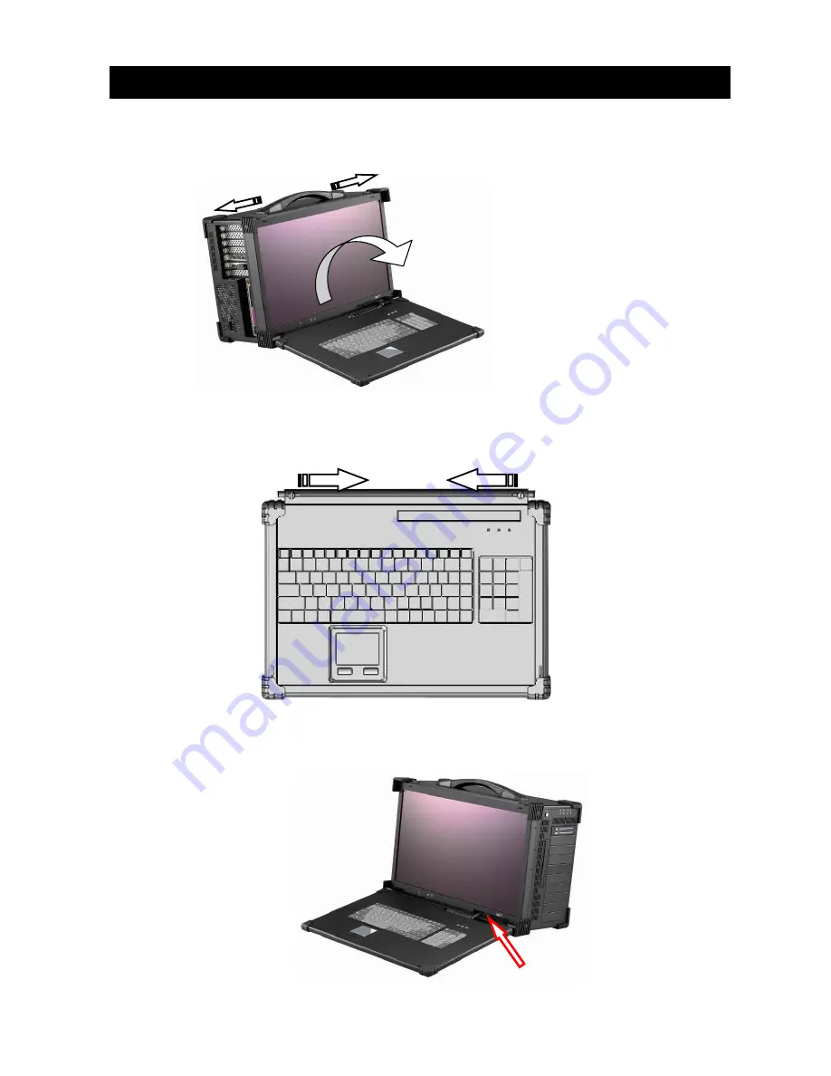
1.  Releasing Keyboard from main unit by pushing the 2 taps located on upside of the chassis to 

release the locking mechanism, and then pull out the keyboard. 


2.  You have the option of leaving the keyboard attached to the chassis or they can be release 

independently from the chassis by pushing the two levers inward to release the lock. 


3.  Connect the RJ-45 keyboard/touchpad cable to the front bottom right corner of the chassis.  

Make sure the pin direction is correct when inserting. 


2.0 Operation


Summary of Contents for ARP 690-P

Page 1: ...ARP 690 P User Reference Manual...

Page 2: ...ycles Keyboard Layout CH FR GR KR RU SP UK US Power Supply PS2 650W 100 240VAC Auto switch Construction Rugged Aluminum Construction with shock absorbing rubber corners Speaker Built in amplified 2x 3...

Page 3: ...ARP690 P 1 ARP690 P Portable Computer Chassis 1 2 Carrying Case with wheels 1 3 User s Manual 1 4 Power Cord 1 5 Anti Static Bag 1 6 Screw Pack stabilizer 1 7 Stabilizer Supports Pack 1 8 9 Standard A...

Page 4: ...tion The display can accommodate the latest graphic card to provide fast refreshing video playback editing and vast desktop space with wide angle viewing capability The chassis have 5x 5 25 drive bays...

Page 5: ...ll out the keyboard 2 You have the option of leaving the keyboard attached to the chassis or they can be release independently from the chassis by pushing the two levers inward to release the lock 3 C...

Page 6: ...e power cable outlet into the power supply unit 6 Press the power switch located on the right side of the chassis to power up the unit The indicator LED lights for Power and HDD activity and reset swi...

Page 7: ...n slots on the left side of the chassis 8 ARP690 provides 10x 3 5 1x slim DVD RW drive bays or 6x 5 25 1x slim DVD RW drive bays 9 Full function keyboard and touchpad surface act as input for the syst...

Page 8: ...before proceeding 1 Open Back Cover 2 Remove the Card stabilizer bar 3 0 Internal Hardware Access Unscrew Unscrew Unscrew Unscrew Unscrew Unscrew Unscrew Unscrew Unscrew Unscrew Unscrew Unscrew Unscr...

Page 9: ...ve bay 10x 3 5 3 1 Remove the right side cover 3 2 Remove the drive bay Slide and remove the 3 5 drive bay Unscrew Unscrew Unscrew Unscrew Unscrew Unscrew Unscrew Unscrew Unscrew Unscrew Slide Move ou...

Page 10: ...3 3 Remove the drive bay Release the bottom of 4x Screws 3 4 Slide and move out the drive bay slowly Slide Move out Unscrew Unscrew Unscrew Unscrew...

Page 11: ...ay 6x 5 25 4 1 Remove the right side cover 4 2 Remove the drive bay Slide and remove the 3 5 drive bay Unscrew Unscrew Unscrew Unscrew Unscrew Unscrew Unscrew Unscrew Unscrew Unscrew Unscrew Unscrew S...

Page 12: ...4 3 Remove the drive bay Release the bottom of 4x Screws 4 4 Slide and move out the drive bay slowly Slide Move out Unscrew Unscrew Unscrew Unscrew...

Page 13: ...5 Remove The Power Supply 5 1 Remove the left side cover 5 2 Slide and move out the PSU slowly Unscrew Unscrew Unscrew Unscrew Unscrew Slide Move out Unscrew Unscrew Unscrew Unscrew Unscrew Unscrew...

Page 14: ...ching the Motherboard into the chassis and correct I O plate supplied by board manufacturer and secure it the motherboard onto chassis 7 Install the drive bay into chassis 8 Install the Power Supply i...

Page 15: ...in the batch file you will usually get a DOS prompt after loading Window Boot up Windows boot up requires you to have Windows installed in the hard disk drive During Windows boot up you will see a seq...

Page 16: ...lay LCD 1 Check all the proper power up procedure has been taken 2 Hook up an external LCD to the VGA port to check if video is present 3 If video is present on external LCD check the internal LCD cab...

Reviews: