Ariesys ARP 690-P User'S Reference Manual Download Page 4


Version: 2012.07 

ARP 690-P features: 


 Aluminum Construction with shock absorbing rubber corners  

 21.5" LCD display support Full HD, 1920x 1080 resolution 

   Anti-reflection tempered glass  

 Support ATX Motherboard, EATX MB (10x 3.5” model) 

 Offer 7-slot expansion capability  

 Industrial multi-languages keyboard with touchpad  

 PS2, 650W power supply, 100~240VAC 

 Offer 10x 3.5", 1x slim DVD-RW drive bay  

   Option: 6x 5.25", 1x slim DVD-RW 

 Anti-reflection tempered glass protect LCD  

 Carrying case to manage portable PC with ease 


The ARP690-P supports standard ATX form factor motherboard as well as Extended ATX motherboard (10x 
3.5” drive bay version only). The chassis can always meet the need of your add-on cards configuration as 
well as processors choice. Whether it is ISA, PCI, PCI-X, PCI-E or combination of all of the above, the 
chassis can be fitted for 7 full-length expansion slots. The chassis comes with integrated 21.5”, 16:9 
widescreen LED backlight LCD panel with 1920x 1080 full HD resolution. The display can accommodate the 
latest graphic card to provide fast refreshing video playback, editing and vast desktop space with wide angle 
viewing capability. 
The chassis have 5x 5.25" drive bays; this allows the chassis to mount large amount of instrumentation 
connections or convert to large amount of removable storage (with aftermarket kit to provide up to 8x 3.5" 
Enterprise SATA/SAS drives or up to 30x 2.5" SATA drives).  Another option is the 10x 3.5" drive bay 
configuration which can also host large amount of storage (up to 20x 2.5" SATA drives) and at the same time 
provide room for Extended ATX form factor dual processors system board.  There is also an integrated slim 
optical drive bay, 2x 120mm cooling fan and a combination keyboard touchpad that folds into the chassis 
and doubles as an additional protection for the display. 
 
Applications: Military, Industrial automation, Digital TV test & analysis, Mobile Computing, Outdoor 
Computers, video conferencing, E-learning, Speech Technologies, Portable Workstation, Telemedicine, 
Multimedia, Mission Critical Computing 


1.0 Introduction


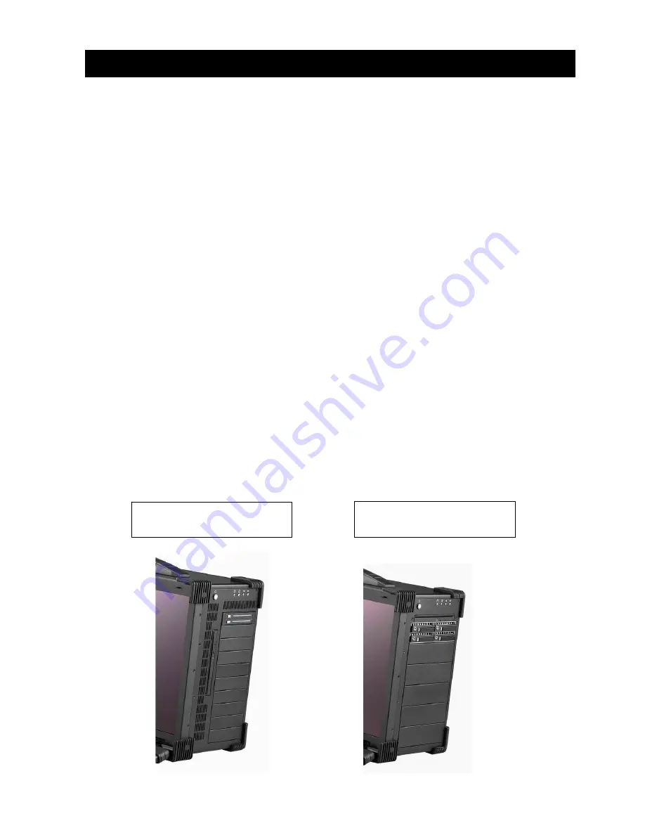
ARP690 with 10x 3.5”, 1 slim 
DVD-RW drive bay 

ARP690 with 6x 5.25”, 1 slim 
DVD-RW drive bay 

Summary of Contents for ARP 690-P

Page 1: ...ARP 690 P User Reference Manual...

Page 2: ...ycles Keyboard Layout CH FR GR KR RU SP UK US Power Supply PS2 650W 100 240VAC Auto switch Construction Rugged Aluminum Construction with shock absorbing rubber corners Speaker Built in amplified 2x 3...

Page 3: ...ARP690 P 1 ARP690 P Portable Computer Chassis 1 2 Carrying Case with wheels 1 3 User s Manual 1 4 Power Cord 1 5 Anti Static Bag 1 6 Screw Pack stabilizer 1 7 Stabilizer Supports Pack 1 8 9 Standard A...

Page 4: ...tion The display can accommodate the latest graphic card to provide fast refreshing video playback editing and vast desktop space with wide angle viewing capability The chassis have 5x 5 25 drive bays...

Page 5: ...ll out the keyboard 2 You have the option of leaving the keyboard attached to the chassis or they can be release independently from the chassis by pushing the two levers inward to release the lock 3 C...

Page 6: ...e power cable outlet into the power supply unit 6 Press the power switch located on the right side of the chassis to power up the unit The indicator LED lights for Power and HDD activity and reset swi...

Page 7: ...n slots on the left side of the chassis 8 ARP690 provides 10x 3 5 1x slim DVD RW drive bays or 6x 5 25 1x slim DVD RW drive bays 9 Full function keyboard and touchpad surface act as input for the syst...

Page 8: ...before proceeding 1 Open Back Cover 2 Remove the Card stabilizer bar 3 0 Internal Hardware Access Unscrew Unscrew Unscrew Unscrew Unscrew Unscrew Unscrew Unscrew Unscrew Unscrew Unscrew Unscrew Unscr...

Page 9: ...ve bay 10x 3 5 3 1 Remove the right side cover 3 2 Remove the drive bay Slide and remove the 3 5 drive bay Unscrew Unscrew Unscrew Unscrew Unscrew Unscrew Unscrew Unscrew Unscrew Unscrew Slide Move ou...

Page 10: ...3 3 Remove the drive bay Release the bottom of 4x Screws 3 4 Slide and move out the drive bay slowly Slide Move out Unscrew Unscrew Unscrew Unscrew...

Page 11: ...ay 6x 5 25 4 1 Remove the right side cover 4 2 Remove the drive bay Slide and remove the 3 5 drive bay Unscrew Unscrew Unscrew Unscrew Unscrew Unscrew Unscrew Unscrew Unscrew Unscrew Unscrew Unscrew S...

Page 12: ...4 3 Remove the drive bay Release the bottom of 4x Screws 4 4 Slide and move out the drive bay slowly Slide Move out Unscrew Unscrew Unscrew Unscrew...

Page 13: ...5 Remove The Power Supply 5 1 Remove the left side cover 5 2 Slide and move out the PSU slowly Unscrew Unscrew Unscrew Unscrew Unscrew Slide Move out Unscrew Unscrew Unscrew Unscrew Unscrew Unscrew...

Page 14: ...ching the Motherboard into the chassis and correct I O plate supplied by board manufacturer and secure it the motherboard onto chassis 7 Install the drive bay into chassis 8 Install the Power Supply i...

Page 15: ...in the batch file you will usually get a DOS prompt after loading Window Boot up Windows boot up requires you to have Windows installed in the hard disk drive During Windows boot up you will see a seq...

Page 16: ...lay LCD 1 Check all the proper power up procedure has been taken 2 Hook up an external LCD to the VGA port to check if video is present 3 If video is present on external LCD check the internal LCD cab...

Reviews: