background image

GB - 19

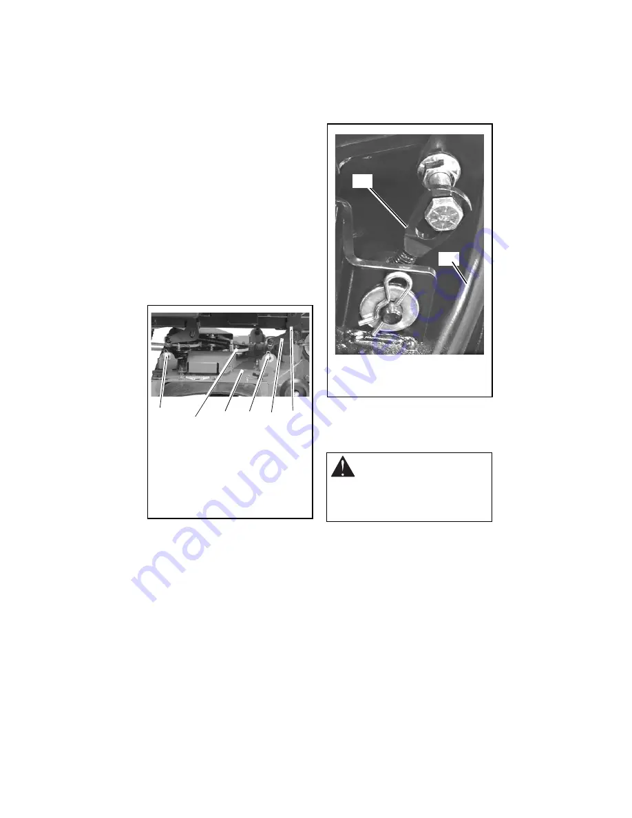
Adjusting The Mower Deck To Adjust 
Mower Blade Height And Pitch 
(Figure 16):

NOTE: Adjusting the mower deck will adjust 
the height and pitch of the mower blades.

1. Adjust the trunnions first and re-take the 

three measurements required to level 
and adjust the pitch of the mower deck. 
These measurements are:

a. The distance from the mower 

blades to the ground.

b. The forward pitch of the mower 

blades.

c. The pitch of the mower blades 

from side-to-side.

2. Repeat step 1 as needed until all three 

measurements are within the tolerances 
specified.

SERVICING BATTERY

NOTE: Unit comes equipped with a 
maintenance-free battery that requires no 
regular maintenance except cleaning the 
terminals and periodic charging.

Battery Removal and Installation

Remove (Figure 17)

1. Tip seat forward (see TIPPING SEAT 

FORWARD on page 16).

2. Disconnect negative (–) cable first, then 

positive (+) cable.

3. Remove battery hold-down bracket and 

battery from unit. 

Figure 15

1

1. Rear Trunnion
2. PTO Belt
3. Mower Deck
4. Drag Link
5. Front Trunnion
6. Lift Arm

2

3

5

4

6

WARNING: Battery posts, 
terminals and related accessories 
contain lead and lead compounds, 
chemicals known to the State of 
California to cause cancer and 
reproductive harm. Wash hands 
after handling.

Figure 16

1. Trunnion
2. Mower Deck

1

2

Summary of Contents for 915137 - 2042 Zoom XL

Page 1: ...Zoom XL Owner Operator Manual Manuel Du Propri taire Utilisateur Models 915137 2042 Zoom XL 915139 2548 Zoom XL ENGLISH 03829100 11 08 Printed in USA ENGLISH FRAN AIS...

Page 2: ...diff rentes langues sont disponibles chez votre revendeur Rendez vous chez votre revendeur ou allez sur le site www ariens com pour consulter la liste des langues disponibles pour votre quipement Les...

Page 3: ...r Note If you have purchased this product without complete assembly and instruction by your retailer it is your responsibility to Read and understand all assembly instructions in this manual If you do...

Page 4: ...if the operator is not alert to the presence of children Never assume that children will remain where you last saw them Gasoline is extremely flammable and the vapors are explosive handle with care D...

Page 5: ...chacun des leviers et boutons de commande Ne jamais permettre l utilisation par des personnes n ayant pas recu la formation necessaire Desenclencher la PdF arreter la machine et le moteur serrer le fr...

Page 6: ...erioration of grass catchers Replace or repair as needed ALWAYS check overhead and side clearances carefully before operation ALWAYS be aware of traffic when crossing or operating along streets or cur...

Page 7: ...t when starting engine ALWAYS keep body and hands away from pin holes or nozzles which eject hydraulic fluid under pressure DO NOT touch unit parts which might be hot from operation Allow parts to coo...

Page 8: ...in effective working order by operator Fuel is highly flammable and its vapors are explosive Handle with care Use an approved fuel container NO smoking NO sparks NO flames ALWAYS allow engine to cool...

Page 9: ...ecessary Never store the machine or fuel container inside a building where there is an open flame such as a water heater Shut off fuel if provided and allow engine to cool completely before storing in...

Page 10: ...Check system before each use to make sure it is functioning properly Figure 3 2 4 3 1 1 Seat 2 Steering Lever 3 Eccentric 4 Handlebar Brackets 3 CAUTION Avoid injury Explosive separation of tire and r...

Page 11: ...ch 3 Throttle Lever 4 Seat 5 Steering Levers 6 Parking Brake 7 Fuel Tanks 8 Mower Lift Pedal 9 Mower Deck 10 Discharge Chute 11 Fuel Gauge 12 Choke Control 13 Hour meter CONTROLS AND FEATURES 4 2 1 3...

Page 12: ...Parking Brake Engages 2 and disengages 1 parking brake Power Take Off PTO Switch Engages 2 and disengages 1 mower blades Hour Meter Records total number of hours engine has been run NOTE Hour meter w...

Page 13: ...wer deck See SPECIFICATIONS on page 28 for cutting height dimensions Press mower lift pedal and install adjustment pin in the desired adjustment hole NOTE Adjusting the seat further forward will help...

Page 14: ...hly before operation IMPORTANT Let the engine warm up several seconds to several minutes depending on outside temperature Stopping the Engine 1 Stop unit 2 Disengage PTO 3 Set throttle lever to slow 4...

Page 15: ...proper operation of unit can result in death or serious injury Test this system each time the unit is operated If this system does not function as described do not operate until repairs are made see S...

Page 16: ...ricate Unit Apply grease to zerk 1 on each front wheel 50 Hours or Every Season Check Fasteners Check mower blade mounting hardware and all other fasteners Replace fasteners that are missing or damage...

Page 17: ...11 1 Block mower blades to prevent rotation 2 Remove mounting hardware and mower blades from mower deck Install Figure 11 1 Install mower blades on mower deck with mounting hardware 2 Torque 5 8 inch...

Page 18: ...es Figure 13 Should be 0 0 in 0 0 mm to 1 4 in 6 35 mm pitched forward NOTE This measurement must be taken when the mower blades ends are facing forward The Pitch Of The Mower Blades From Side To Side...

Page 19: ...s specified SERVICING BATTERY NOTE Unit comes equipped with a maintenance free battery that requires no regular maintenance except cleaning the terminals and periodic charging Battery Removal and Inst...

Page 20: ...PORTANT DO NOT fast charge Charging at a higher rate will damage or destroy battery IMPORTANT ALWAYS follow information provided on battery and battery charger Contact battery and battery charger manu...

Page 21: ...avel in a straight line 1 Determine which way the unit turns NOTE The forward travel adjustment bolt adjusts the rear travel of the steering lever The rear travel adjustment bolt adjusts the forward t...

Page 22: ...nstall hydrostatic belt on idler electric clutch pulley and hydrostatic transmission pulleys 2 Connect idler spring 3 Install clutch stop 4 Connect electric clutch connector 5 Install PTO belt see REP...

Page 23: ...llow the instructions in To Add Hydraulic Fluid on page 22 Purging the Hydraulic System 1 With the unit up to and facing a wall jack up the unit so that both drive wheels are off the ground 2 Disengag...

Page 24: ...ilizer container To treat the fuel system for storage 1 Add fuel stabilizer according to manufacturers s instructions 2 Run engine for at least 10 minutes after adding stabilizer to allow it to reach...

Page 25: ...ealer 3 Electric clutch connector is loose or disconnected 3 Connect the electric clutch connector See REPLACING HYDROSTATIC BELT on page 22 for the electric clutch connector location 4 Faulty PTO bel...

Page 26: ...ntact your Ariens Dealer Unit creeps with steering levers in neutral position 1 Hydrostatic transmission and or linkage needs adjustment 1 Contact your Ariens Dealer Poor cutting quality 1 Mower deck...

Page 27: ...h Mulching Blade 02970100 1 Battery 07242200 1 Hydrostatic Belt 07200037 1 42 Inch PTO Belt 07200436 1 48 Inch PTO Belt ACCESSORIES See your authorized Ariens dealer to add these optional accessories...

Page 28: ...e PTO Power Take Off Electric Clutch Brake Fuel Fuel Type Refer to Engine Manual Fuel Tank Capacity gal L 4 5 17 0 Transmission Hydrostatic Drive Size and Weight Length in cm 68 173 Width in cm 56 142...

Page 29: ......

Page 30: ...rd through fifth year from the date of purchase the parts required to repair a defect in material or work manship of the main frame not the labor will be provided free of charge 90 Day Limited Warrant...

Page 31: ...purchased in the United States including Puerto Rico and Canada In all other countries contact place of purchase for warranty information Disclaimer Ariens may from time to time change the design of...

Page 32: ...Ariens Company 655 West Ryan Street Brillion WI 54110 1072 920 756 2141 Fax 920 756 2407 www ariens com...

Reviews: