background image


User’s Manual                                                            

10


2.3  Installing, Replacing and Charging Batteries 

 
Wrong use of batteries may cause serious damage to the mobile computer or to the cradle. To 
avoid damage, it is important to follow the instructions. 


Caution: 



Insert  a  fully-charged  battery  pack  before  use  of  the  mobile 
computer.




Never remove the main batteries while the mobile computer is turned 
on.


Doing so may lose data that is not saved in the mobile computer.




Use only recommended batteries.


When  other  batteries  are  used,  defects  or  other  problems  can  occur. 
Before  installing  (new)  batteries,  please  make  sure  you  are  using  the 
recommended batteries. 
 



Use the right charger for batteries.


The rechargeable Li-polymer battery pack from Argox can be charged in 
the  cradle  when  either  it  is  in  the  mobile  computer  or  alone  in  the 
charging slot in the back of the cradle. 
 



The  life  of  a  battery  pack  is  limited,  and  charging  a  battery  pack 
causes  it  to  gradually  lose  its  ability  to  maintain  a  charge.  If  your 
battery pack requires frequent charging, it probably means it is time 
to purchase a new one.




A  fully  charged  backup  battery  can  maintain  memory  (RAM) 
contents  for  about  15  minutes,  even  when  the  battery  pack  is 
removed.




Strictly follow the instructions for installing, charging, and removing 
the batteries.


The products are not warranted for damage, defects, malfunction, or loss of 
data, resulting from incorrect use of batteries.


Required batteries: 

The mobile computer needs both main battery and backup battery for operation. 


Main Battery 

The  rechargeable  battery  pack  is  for  normal  operations  and  data  storage.  When  the  battery 
pack power goes low, immediately charge it or replace it with a charged battery pack. 


Summary of Contents for PT-9 Series

Page 1: ...User s Manual PT 9XXX X X Mobile Computer WinCE 6 0 version DOC NO UM P9005 01 Mar 2010 Version 1 0 Empower the Bar Code ...

Page 2: ...ut the possibility of such damages A serial number appears on all Argox products This official registration number is strictly related to the device purchased Make sure that the serial number appearing on your Argox device has not been removed Servicing by our service department can only be carried out under warranty All Argox products are warranted for the legal warranty period after purchase cov...

Page 3: ...PTION 15 3 2 FUNCTION KEY DESCRIPTION 16 3 3 INSTALL MICRO SD CARD INTO PT 90 17 3 4 CONFIGURING PT 90 SETTINGS 18 3 4 1 Calibrating Touch Screen Alignment 18 3 4 2 Adjusting Brightness 19 3 4 3 Muting Sound 19 3 4 4 Using the Stylus 19 3 5 ENTERING INFORMATION 20 3 5 1 Entering Information Using a Keypad 20 3 5 2 Entering Information Using the Keyboard Input Panel 20 3 5 3 Entering Data via the B...

Page 4: ...NG UP THE PT 90 50 8 3 1 Certificates 51 8 3 2 Date Time 52 8 3 3 Dialing 53 8 3 4 Display 54 8 3 5 Hot Function Key 55 8 3 6 Input Panel 55 8 3 7 Internet Options 56 8 3 8 Keyboard 57 8 3 9 Mouse 58 8 3 10 Network and Dial up Connection 58 8 3 11 Owner 59 8 3 12 Password 60 8 3 13 PC Connection 61 8 3 14 Power 62 8 3 15 Regional Settings 62 8 3 16 Remove Programs 63 8 3 17 Scan Configuration 64 8...

Page 5: ...ansflective type color LCD display Backlight keypad 1 1 About this Manual The chapters contained in this manual are Chapter 1 Introduction Presents general information about the PT 90 Chapter 2 Getting started Describes basic use of the PT 90 Chapter 3 Operating the Mobile computer Describes customizing the PT 90 Chapter 4 Scanning Chapter 5 Useful Utilities Chapter 6 Software Applications Chapter...

Page 6: ... drained battery Lithium ion battery packs may get hot explode ignite and or cause serious injury if abused Please follow the safety warnings listed below Warnings Do not place the battery pack in fire or heat the battery Do not install the battery pack backwards so the polarity is reversed Do not carry or store battery pack together with metal objects Do not pierce the battery pack with nails str...

Page 7: ...timal charging capacity Do not use water when cleaning the cradle This can cause malfunction of the chargers Using the Mobile Computer Avoid temperature changes Sudden temperature changes can cause condensation to form on the mobile computer Using the mobile computer while condensation is present can cause malfunction Always wait until the condensation clears naturally before attempting operation ...

Page 8: ...ATA 2 5 TRI OPTIC and RSS Keypad 29 keys 29 keys plus 44 keys with backlight Communication Interface Standard Interface USB 2 0 and RS 232 Wireless radio Options WPAN Bluetooth Class 2 version 2 0 WLAN 802 11b g Wi Fi GPS SiRF star III TBD Power supply Main power Terminal Rechargeable Li ion Battery 3900mAH 3 7Vdc Gun type Rechargeable Li ion Battery 4400mAH 3 7Vdc Power input Via cradle or direct...

Page 9: ... meters to concrete Handset 0 9 meters to concrete Cradle ESD 15kVDC air discharge 8kVDC direct discharge contact 8kVDC indirect discharge H V Sealed standard IP65 Agency Listing CE FCC BSMI NCC CCC SRRC Win CE AP MS Web Browser Internet Explorer Media Player Microsoft WordPad Remote Desktop Connection Transcriber Windows Explorer Developing Tools Argox SDK Microsoft Visual Studio for smart device...

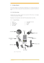
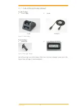
Page 10: ...ully remove all protective material from around the PT 90 and save the shipping container for later storage and shipping Depending on the configuration ordered the PT 90 shipping container may include 2 1 1 Compact Package PT 90 Quick Reference Guide Battery pack CD ROM USB Sync cable Thread Power supply Stylus Hand strap Figure 2 1 Compact Package Battery pack Thread USB Sync cable Power supply H...

Page 11: ...er supply Cradle Figure 2 2 Cradle Package Pistol Package pistol grip Li ion battery 4400mAH Figure 2 3 Pistol grip Package Inspect the package contents for damage If any item is missing or damaged please contact the Argox Technical Support Center immediately USB cable Cradle ...

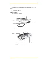
Page 12: ...ports and other functions 2 2 1 PT 90 Mobile Computer Dimensions of the PT 90 159 mm L 80 8mm W 36mm H Figure 2 4 The Front of the PT 90 Figure 2 5 The Back of PT 90 Hand strap Docking Connector Micro SD Card slot Battery Cover Latch Scan Button Key pad Scan Window Stylus Scan Button Touch Screen Speaker ...

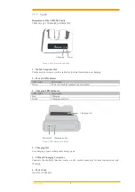
Page 13: ...us Description Green Power on mobile computer not in cradle 3 Charging LED Indicator LED status Description Red Charging Green Charging complete Figure 2 7 The Back of the CRD 90 4 Charging Slot For charging a spare rechargeable battery pack 5 USB and Charging Connector Connects the multiple function socket on the mobile computer for data transmission and charging 6 Power Jack Input for AC adapter...

Page 14: ...hen either it is in the mobile computer or alone in the charging slot in the back of the cradle The life of a battery pack is limited and charging a battery pack causes it to gradually lose its ability to maintain a charge If your battery pack requires frequent charging it probably means it is time to purchase a new one A fully charged backup battery can maintain memory RAM contents for about 15 m...

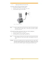
Page 15: ...f the cradle The LED CHG on the cradle flashes Red and turns Green when the battery is fully charged When to replace or recharge the main battery There are two conditions that you need to replace the main battery 1 As soon as possible after the battery indicator appears on the display 2 Before using the mobile computer when it has not been used for an extended period Notes Charging the Main and Ba...

Page 16: ... 4 Align the battery contacts and insert the battery 5 Reassemble the battery cover and Rotate the latches to the closed position 2 3 2 Charging the Battery Pack with a Power Adapter Using a RS232 Charging Cable or USB Charging Cable 1 Plug in the RS232 Charging cable or the USB Charging cable to the PT 90 2 Connect the AC adapter to the cable s power jack and an electrical outlet Figure 2 9 Suppl...

Page 17: ...k into the Cradle s spare battery charging slot 1 Connect the power adapter to a power source 2 Plug in the connector of the power adapter with Cradle 3 Insert the battery pack into the Cradle s spare battery slot Note When charging the battery pack in the Cradle s spare battery slot the Cradle charging LED is Red After the battery pack is fully charged the LED turns green Caution Do not remove th...

Page 18: ...ble for some cases contact your supplier to purchase the right cables or technical support System Connection Data Communication The mobile computers let you link to a host computer through USB and RS 232 cable or the CRD 90 cradle for data communication 2 4 1 Via USB RS 232 Cable The mobile computer connects directly to a host computer via the USB RS 232 cable Figure 2 11 Communication through Cab...

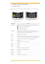
Page 19: ... key turns the unit on Alternatively when the unit is on this key must be pressed and held down for about two seconds in order to turn the unit off ESC Exit and back to the last layer TAB The Tab key is used to toggle between data fields or to place the cursor at pre determined places in a programming or word processing application BKSP The Backspace key is used to erase previously input character...

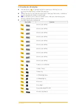
Page 20: ...on key twice function continue mode After press function key again function continue mode switches to normal Available function key combinations Key Define Function Reserve user define Reserve user define Reserve user define Reserve user define Reserve user define Reserve user define Reserve user define Reserve user define Reserve user define Reserve user define Touch screen calibration Volume Dow...

Page 21: ... correctly oriented Micro SD card 3 Close the slot cover and fix two screws Note a If the micro SD card is inserted incorrectly the micro SD card unit and its internal data maybe damaged b When removing the micro SD card please press push first Insert Micro SD card face side down Figure 3 2 Inserting a micro SD Card ...

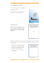
Page 22: ...tart Settings Control Panel Stylus Calibration Figure 3 4 Calibration 1 Whenever the response of the touch screen is poor or the operations executed do not match your tapping on the touch screen please recalibrate the alignment of the touch screen using the following method 1 Press the stylus against the center of the target mark as indicated on the screen The screen shown to the right appears aft...

Page 23: ...onditions Press the key and then press the key to adjust for a louder sound Press the key and then press the key to adjust for a softer sound To continue making adjustments press the key twice to enter function continue mode Press the or key to adjust sound After finish setting press the key to exit function continue mode Sound settings are also be made by accessing the menu and tab in order of St...

Page 24: ... character alphabet A Z number s 0 9 function keys and assorted characters The keypads default characters functions are printed white 3 5 2 Entering Information Using the Keyboard Input Panel Use the keyboard input panel soft keyboard to enter information in any program To launch the keyboard input panel press the button on the taskbar Tap a key to enter a value Tap a key board input panel button ...

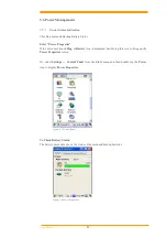
Page 25: ...ug or Battery icon is displayed double tap this icon to bring up the Power Properties screen Or select Settings Control Panel from the Start menu and then double tap the Power icon to display Power Properties Figure 3 7 Control Panel To Check Battery Status The battery menu item shows the status of the main and backup batteries Figure 3 8 Power Properties ...

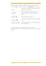
Page 26: ... PT 90 is either plugged in via the DC 5V 3A power adapter or in the cradle Charging Indicates that the battery is charging Battery Low Shows there is no external power supply the battery charge is low Battery Very low Indicates the battery is very low Stop operation and charge the PT 90 immediately You must charge the battery when the Battery Very Low icon is displayed If the Battery Very Low ico...

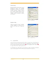
Page 27: ...he available time periods for battery power are 1 2 3 4 5 10 30 minutes and never Activate this function when the PT 90 is plugged into the power adapter or placed in its cradle by tapping the check box and then tapping the arrow to select from a list of time periods The available time periods for AC power are 1 2 5 10 15 30 minutes and never Figure 3 9 Power Properties 2 Backlight Setting Because...

Page 28: ...etting for backlight Available brightness for battery and AC power are Off Micro Fine Normal and Super Figure 3 12 Brightness Setting 3 6 3 Suspend Mode The PT 90 will go into suspend mode when it is idle for a period of time Customize the idle duration using the Power control panel refer to Figure Schemes Tab Suspend mode appears just like you have turned the unit off Press the key to suspend the...

Page 29: ...us Description Condition for Wakeup Power Off When the PT 90 is set to suspend mode by pressing this action wakes the PT 90 Press button Auto Off When the PT 90 enters suspend mode by automatic power off this action wakes the PT 90 Press button 3 7 Resetting the PT 90 If the PT 90 stops responding to the system you may need to rest it There are three ways to reset warm boot cold boot and clean boo...

Page 30: ...rm a cold boot Perform a clean boot only if you want to reset PT 90 to factory default setting Caution All data will be lost The Utility programs are also lost We recommend that copy 90Utility cab to micro SD and insert into PT90 before perform a clean boot After clean boot OS will install 90Utility cab automatically from micro SD To perform a clean boot in OS 1 To perform a clean boot select Star...

Page 31: ...e memory persists for warm cold reset conditions We strongly recommend that perform a clean reset only if you want to reset factory default setting 3 8 1 Flash Disk Location All storage disk is stored in Flash Disk in PT 90 Figure 3 15 My Device 3 8 2 Flash Disk Size The size of the Flash Disk varies depending on the size of the system firmware Select Start Settings Control Panel and then double t...

Page 32: ...ng 1 Please enable Bluetooth first like Figure 3 17 Figure 3 17 Enable Bluetooth 2 After enable Bluetooth please select Show BT like figure 3 18 Figure 3 18 Show BT 3 On Bluetooth manager screen select File New Connection like Figure 3 19 ...

Page 33: ...User s Manual 29 Figure 3 19 Bluetooth Connection ...

Page 34: ...remote device after press next button It will start to search devices Select a device and press Pair button it needs to enter Bluetooth PIN code like Figure 3 21 Figure 3 21 Bluetooth Pairing 6 After PT 90 check pin code with device PT 90 will appear a pop window and show Success message like Figure 3 22 Figure 3 22 Bluetooth Pairing 1 ...

Page 35: ... com port like Figure 3 23 Figure 3 23 Bluetooth Explorer 8 After press Next button it will start to search device like Figure3 24 Figure 3 24 Bluetooth Serial Port 9 After press Connect button it will appear a connection with SPP mode like Figure 3 25 Figure 3 25 Bluetooth Serial Port ...

Page 36: ...ooth Explorer 11 After press Next button it will start to search device and it needs to enter PIN code like Figure 3 27 Figure 3 27 Bluetooth File Transfer 1 12 After checking pin code with the connect device PT90 will enter FTP mode like Figure 3 28 Figure 3 28 Bluetooth File Transfer 2 ...

Page 37: ...Figure 3 29 Bluetooth File Transfer 3 14 The latest function is ActiveSync connection The function can connect with computer via ActiveSync like Figure 3 30 Figure 3 30 Bluetooth Explorer 15 After press Next button it will start to search device like Figure 3 31 Figure 3 31 Bluetooth ActiveSync ...

Page 38: ...User s Manual 34 16 PT 90 will add a ActiveSync connection on Bluetooth manager screen It will synchronize with computer like Figure 3 32 Figure 3 32 Bluetooth ActiveSync ...

Page 39: ... new connection and press Connect button or double click the new connection BU01 WPA for instance it will appear the configuration window Figure 3 34 Then user can set wireless Encryption on this window Figure 3 34 Wireless Properties 4 After setting press OK to connect to AP server wireless AP server must setup completely before connection WiFi connection can work now 5 Wireless icon Icon Descrip...

Page 40: ...ctivate the laser scanner 4 1 Scan Configuration When it is necessary to change the default barcode symbology for a different application use Scan Configuration to change default symbology place delimiter characters behind scanned data and save the settings Run this program from Desktop Utility Scan Configuration exe which is also accessible via Start Settings Control Panel Scan Configuration Figu...

Reviews: