background image


A Series User’s Manual 


57 

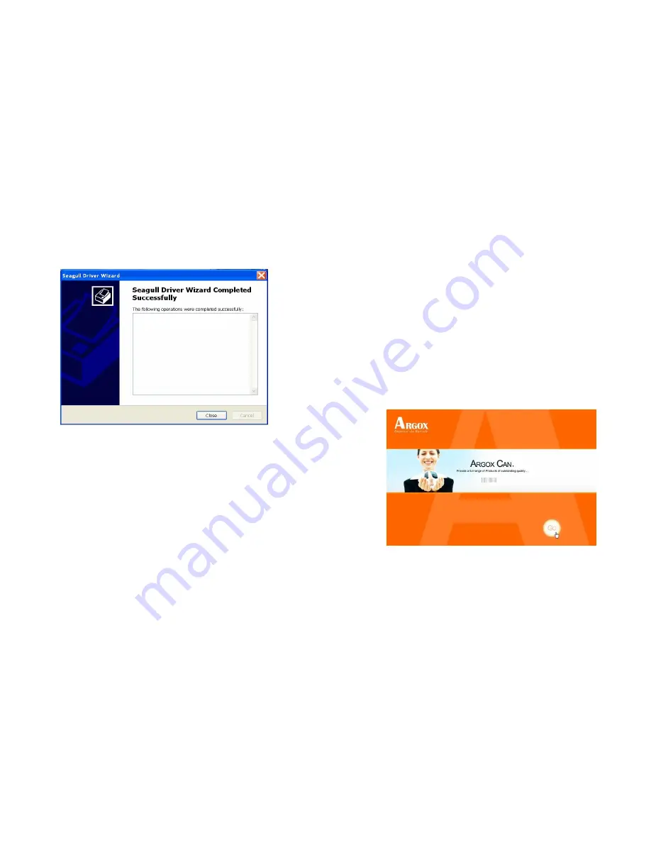
9.  After driver installation is complete, click "Close". 

The driver should now be installed.


Installed printer Argox A-2240 PPLB 


A Series User’s Manual 


58 

Installing the Printer Driver   


1.  Turn off the printer. Plug the power cable into the power 

socket on the wall, and then connect the other end of the 
cable to printer's power socket. Connect the USB cable, Serial 
cable, or Ethernet cable to the proper port on the printer and 
on your computer. 
 

2.  Prepare the documentation and software DVD-Rom from 

printer package and then install to DVD-Rom drive of your 
computer. The DVD-Rom will bring out the following prompt. 
Click “Go”:   


Summary of Contents for A-2240

Page 1: ... not installed and used in accordance with the instructions may cause harmful interference to radio communications However there is no guarantee that the interference will not occur in a particular installation If this equipment does cause harmful interference to radio or television reception which can be determined by turning the equipment off and on the user is encouraged to try to correct the i...

Page 2: ...classe A de la norm Industrielle Canadian Supplemental Information This device complies with the requirement of FCC Part 15 Rules Operation is subject to the following two Conditions 1 This device may not cause harmful interference and 2 this device must accept any interference received including interference that may cause undesired operation Please only use adapters with the following electrical...

Page 3: ... DetectionArea of the Reflective Sensor 44 Computer Connections 45 USB Interface Requirements 45 Serial RS 232 Interface Requirements 46 Serial Cabling Requirements 46 Ethernet 10 100 Internal Printer Server Option 48 Communicating with the Printer 50 Installing a Plug and Play printer driver for USB only 51 Installing the Printer Driver 58 A Series User s Manual 6 Troubleshooting 70 LED Diagnosis...

Page 4: ...e printer Unpacking After receiving your printer please check for possible shipping damage 1 Inspect the outside of both the box and the printer for possible damage 2 Open the top cover of the printer to see if the media compartments are in order Note If damage has occurred contact your shipping company immediately to file a claim A Series User s Manual 8 Package Contents Printer Quick Installatio...

Page 5: ... an area where they might get wet 1 Make sure the power switch is in the O position 2 Insert the barrel connector of the power supply into the power jack on the back of the printer 3 Insert the separate power cord into the power supply 4 Plug the other end of the cord into an AC electrical outlet A Series User s Manual 10 A 2240 A 3140 A 2240M ...

Page 6: ...0E A 2240ME A Series User s Manual 12 Getting to Know Your Printer The illustrations that follow describe the printer s parts features controls and indicators Parts and Features Top Cover Power Switch Power Indicator Ready Indicator Feed Button ...

Page 7: ...on Supply Holder Thermal Printhead A Series User s Manual 14 Controls and Indicators The printer s controls and indicators are shown in the diagram below The following table explains control and indicator functions Top Cover Power Switch Power Indicator Ready Indicator Feed Button ...

Page 8: ...tatus monitor Feed Button Press to advance the label media to the first printing position Press to take the printer out of pause Press and hold while turning on the power to print out a configuration profile A Series User s Manual 16 Loading Ribbon and Media This section describes how to load ribbon and media in the Amigo Series printers Loading a Ribbon Note This section does not apply to direct ...

Page 9: ...s User s Manual 18 4 Unwrap the ribbon roll pack and separate the ribbon roll and the bare core 5 Attach the edge of the ribbon on the bare core and wind it a little bit onto the core 6 Insert the ribbon roll into the supply holder First snap in the right side and then the left side Ribbon Roll Bare Core ...

Page 10: ...e core into the pick up holder First snap in the right side then the left side A Series User s Manual 20 8 Turn the wheel of the print head module to ensure the ribbon is tightly wound 9 Press down the print head module on both sides firmly till you hear a snap Wheel Print Head Module ...

Page 11: ... the label as it prints After the label is removed the next label prints Cutter mode automatically cuts the label after it prints Standard Mode 1 Lift the top cover to expose the media compartment A Series User s Manual 22 2 Remove the media hanger 3 Load the media roll onto the hanger 4 Unlatch the print head module 5 Open the front cover to allow the labels pass through the slot Media Compartmen...

Page 12: ...gh the media guides with the other hand The media guide can be adjusted centrally to fit with different label widths Media Guides A Series User s Manual 24 7 Press the print head module down firmly on both sides until you hear a snap Print Head Module ...

Page 13: ... Close the top cover and turn on the printer or press the feed button if the printer is already on Feed Button A Series User s Manual 26 Peel Off Mode 1 Unscrew the two screws behind the front cover 2 Remove the front cover Screw ...

Page 14: ...spenser connecter 4 Mount the dispenser module Dispenser Connecter Dispenser Module A Series User s Manual 28 5 Secure the two screws behind the front cover 6 Lead the labels through the media guides and dispenser Media Guides Dispenser Screws ...

Page 15: ...inter or press the feed button if the printer is already on Feed Button A Series User s Manual 30 9 Press the feed button and the label backing paper will come out from the slot under dispenser Note The feed button does not make the printer peel Peeling occurs only when the software is properly set Label Backing Paper Feed Button ...

Page 16: ...oard to J16 on the main board 1 Turn off the POWER switch 2 Unscrew the two screws behind the front cover 3 Remove the front cover Front Cover Screw A Series User s Manual 32 4 Loose the 2 screws on the printer bottom 5 Pull out front side of Middle Cover then remove it from Bottom 6 Take out Middle Cover Screw ...

Page 17: ...A Series User s Manual 33 A Series User s Manual 34 7 Remove the whole print head assembly by releasing the 4 screws at its feet 8 Plug the cutter baby board to J16 on the main board J16 ...

Page 18: ...ull the front side of Middle Cover to put it back 10 Screw the 2 screws on the printer bottom 11 Unscrew the screw on the printer module 12 Remove the tear off bar Tear Off Bar A Series User s Manual 36 13 Plug in the cutter connecter 14 Mount Cutter module and install cutter module completely ...

Page 19: ...rough the media guides and cutter slot 16 Press down the print head module firmly on both sides until you hear a snap A Series User s Manual 38 Note The feed button does not make the printer cut Cutting occurs only when the software is properly set Feed Button ...

Page 20: ...des firmware version ROM checksum RS 232 thermal transfer direct thermal settings hardware configuration and font types 6 At PPLB emulation the printer enters character dump mode To exit from dump mode press the feed button again If you accidentally print the label without exiting from dump mode in advance you need to turn on the printer or press feed button again to print normally S Important You...

Page 21: ...media calibration and then print configuration self test labels 3 Once Power indicator becomes lit again release the FEED button 4 Ready indicator will then become lit too At this moment the printer has resumed its factory default settings Note Revise the factory default settings that stored in flash even if turn off the power source cannot be eliminated A Series User s Manual 42 Sensor Detection ...

Page 22: ...e centre of the media The detection area as illustrated below A Series User s Manual 44 Detection Area of the Reflective Sensor The reflective Sensor edge is positioned at 5 65mm from the left edge of media The black mark minimum width horizontal should be 10mm on the left edge of media The detection area as illustrated below ...

Page 23: ...plug and play design makes installation easy Multiple printers can share a single USB port hub A Series User s Manual 46 Serial RS 232 Interface Requirements The required cable must have a nine pin D type male connector on one end which is plugged into the mating serial port located on the back of the printer The other end of the signal interface cable connects to a serial port on the host compute...

Page 24: ...Printer Server Option This connector is for Ethernet application it is convenient to use several printers by Ethernet connector at the same time Notes When using Ethernet model printer please wait till the Ready Indicator to stop blinking and then can start to use printer Power Cord A 2240E A 2240ME ...

Page 25: ...th the Printer The bundled printer driver can be applied to all applications under Windows XP Vista Windows 7 supporting 32 bit 64 bit operation systems With this driver you can operate any popular Windows software applications including Argox Bartender UL label editing software or MS Word etc to print to this printer The following installation steps are based on A 2240 as an example The screens i...

Page 26: ...l and do not install the driver using this wizard 3 Prepare the documentation and software CD Rom from printer package and then install to CD Rom drive of your computer The CD Rom will bring out the following prompt Click Go Note We strongly recommend that you use the Seagull Driver Wizard instead of the Microsoft Windows Add Printer Wizard when installing and updating your Drivers by Seagull Even...

Page 27: ...lation Directory where the Seagull driver files are located 5 On the Seagull Driver Wizard prompt select the first radio button to Install a driver for a Plug and Play printer Then click Next Argox A 2240 PPLB A Series User s Manual 54 6 Enter Printer name i e Argox A 2240D PPLB and select do not share this printer and click Next Argox A 2240 PPLB ...

Page 28: ...data on the showing screen if it is correct click Finish Argox A 2240 PPLB Argox A 2240 PPLB USB002 7 1 9_M 5 A Series User s Manual 56 8 After the related files have been copied to your system click Finish Installing printer Argox A 2240 PPLB ...

Page 29: ...e printer Plug the power cable into the power socket on the wall and then connect the other end of the cable to printer s power socket Connect the USB cable Serial cable or Ethernet cable to the proper port on the printer and on your computer 2 Prepare the documentation and software DVD Rom from printer package and then install to DVD Rom drive of your computer The DVD Rom will bring out the follo...

Page 30: ...then start installation Instead of the flash prompt above another way to install Seagull driver is to run the DriverWizard utility from the Installation Directory where the Seagull driver files are located A Series User s Manual 60 4 On the prompt Windows Printer Driver select I accept and click Next ...

Page 31: ...A Series User s Manual 61 5 Assign the directory to keep Seagull driver for example C Seagull and click Next A Series User s Manual 62 6 Click Finish ...

Page 32: ...A Series User s Manual 63 7 Select Install printer drivers and Click Next A Series User s Manual 64 8 Select model emulation the following examples are based on model A 2240 PPLB Argox A 2240 PPLB ...

Page 33: ...es User s Manual 65 9 Select the port of the printer and click Next A Series User s Manual 66 10 Enter Printer name i e Argox A 2240 PPLB and select do not share this printer and click Next Argox A 2240 PPLB ...

Page 34: ...data on the showing screen if it is correct click Finish Argox A 2240 PPLB Argox A 2240 PPLB USB001 7 1 9_M 5 A Series User s Manual 68 12 After the related files have been copied to your system click Finish Installing printer Argox A 2240 PPLB ...

Page 35: ...If the Power and Ready LEDs are blinking it means you may have a problem To understand the problem please check the Power and Ready LEDs and refer to the following solutions LED Indicators Power and Ready LEDs blink at the same tempo Power LED Ready LED ON ON OFF OFF Possible Problems Solutions Remarks Miss detect gap Check the label path Check the label sensor If you use a continuous label roll a...

Page 36: ...heck the baud rate Serial interface only Memory full Add the extension RAM flash memory card Cutter failed or jam at cutter Check the cutter Recover the jam Occurs only when installing or setting the cutter Hardware error Call for service A Series User s Manual 72 LED Indicators Only the Ready LED blinks Power LED Ready LED ON ON ON OFF Possible Problems Solutions Remarks Print head too hot Printi...

Page 37: ...l printer has been selected Vertical streaks in the printout usually indicate a dirty or faulty print head Refer to the following examples Clean the print head If the problem persists replace the print head A Series User s Manual 74 Poor printout quality The ribbon may not be qualified The media may not be qualified Adjust the Darkness heat temperature Slow down the print speed Refer to the next c...

Page 38: ...cleaned with alcohol A Series User s Manual 76 TPH Cleaning Interval It s strongly recommended to regularly clean print heads at least when changing every one ribbon roll in thermal transfer printing mode or every one label roll in direct thermal printing mode In addition if printers are operated under critical applications and environments or it s found print quality is degraded please clean prin...

Page 39: ...ed altered defected or made illegible under every circumstance A Series User s Manual 78 Replacing Thermal Print Head 1 Turn off the power and wait for both LEDs to go off 2 Push the print head module and pull it down as shown by the two arrows below This releases the print head module from the printer chassis Push ...

Page 40: ...ent 1 Heater line should NOT be touched by bare hands to prevent any damage caused by ESD or corrosion 2 Surface of heaters should NOT be hit or scratched by sharp or hard things to prevent any damage by scratch 3 Residue or contamination should NOT be removed by a cutter to prevent any damage by dent or scratch 4 Connector side should NOT be touched when cleaning TPH to prevent delaminated solder...

Page 41: ...h check sum digit Code 93 EAN 13 EAN 8 Standard 2 5digit add on Codabar Postnet Code128 subset A B C Code 128 UCC shipping container code Code 128 auto UCC EAN code 128 GS1 128 Interleave 2 of 5 Interleaved 2 of 5 with check sum Interleaved 2 of 5 with human readable check digit German Postcode Matrix 2 of 5 UPC Interleaved 2 of 5 EAN 13 2 5 digit add on UPCA 2 5 digit add on UPCE 2 5 digit add on...

Page 42: ... host can communicate with your printer Printer Programming Language A PPLA Programming Language PPLA Internal fonts 9 fonts with different point size 6 fonts with ASD smooth font Courier font with different symbol sets Symbol sets Code pages Courier font symbol set Roman 8 ECMA 94 PC PC A PC B Legal and PC437 Greek Russian Soft fonts Downloadable soft fonts Font size 1x1 to 24x24 times Character ...

Page 43: ...able check digit German Postcode Matrix 2 of 5 UPC Interleaved 2 of 5 EAN 13 2 5 digit add on UPCA 2 5 digit add on UPCE 2 5 digit add on GS1 Data bar RSS MaxiCode PDF417 Data Matrix ECC 200 only QR code Composite Codes Aztec Barcode A Series User s Manual 86 Printer Programming Language Z PPLZ Programming Language PPLZ Internal fonts 8 A H fonts with different point size 8 AGFA fonts 7 P V fonts ...

Page 44: ... data signaling pair 4 GND Ground 1 2 3 4 1 2 3 4 USB series B Receptacle Interface A Series User s Manual 88 Serial The RS232 connector on the printer side is a female DB 9 Pin Direction Definition 1 Shorted to Pin 6 2 In RxData 3 Out TxData 4 N C 5 Ground 6 Shorted to Pin 1 7 Out RTS 8 In CTS 9 Out 5V Note Pin 9 are reserved for KDU keyboard device unit therefore do not connect these pins if you...

Page 45: ...mpatible DTR 20 1 DSR DTR 4 1 DSR DSR 6 6 DTR DSR 6 6 DTR TX 2 2 RX TX 3 2 RX RX 3 3 TX RX 2 3 TX CTS 5 7 RTS CTS 8 7 RTS RTS 4 8 CTR RTS 7 8 CTS GND 7 5 GND GND 5 5 GND Alternatively you can just connect the 3 wires in the following way Host 25S Printer 9P Host 9S Printer 9P PC or compatible PC or compatible TX 2 2 RX TX 3 2 RX RX 3 3 TX RX 2 3 TX GND 7 5 GND GND 5 5 GND pin 4 pin 4 pin 5 pin 6 p...

Page 46: ... non parity Handshaking XON XOFF as well as CTS RTS hardware flow control If you run an application with the bundled printer driver under Windows and use the serial port you should check the above parameters and set the flow control to Xon Xoff or hardware A Series User s Manual 92 Appendix I Installing the Extension Card Extension Card designated for all optional extension modules For example RTC...

Page 47: ...Manual 94 5 Mount the extension card to J14 on the main board Note RTC card Dip switch on DIP 5 should be put on OFF position Add on card Dip switch on DIP 5 should be put on On position 6 Click back the middle cover 7 Secure the two screws for the base housing 8 Click the top cover into place ...

Reviews: