


ASURO - 23 -
5.2.2 Linux
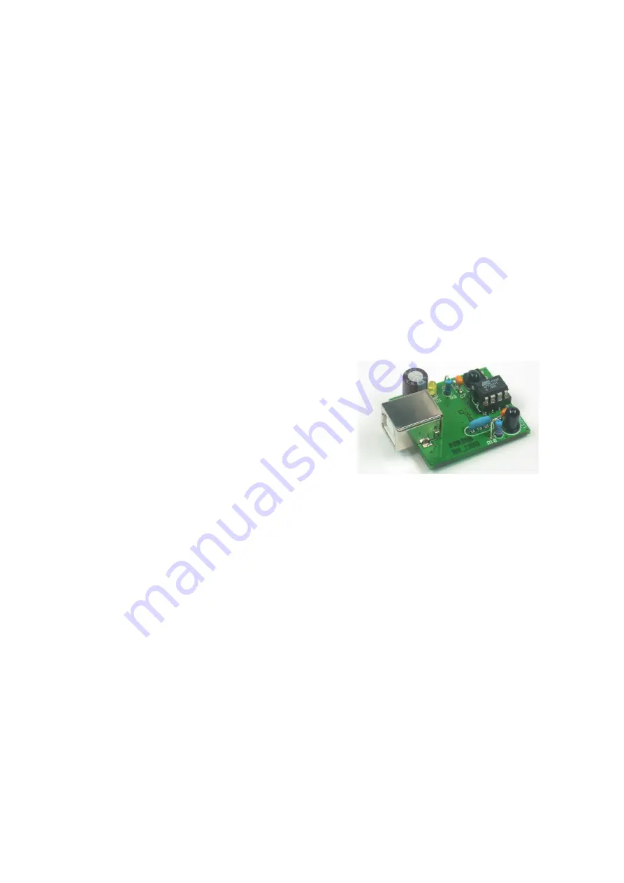
The following operational check is limited to the USB Infrared-Tranceiver and LINUX software.
First of all the IR-Transceiver must be checked, as it will be needed for the next step: the selftest
of the system. For this test connect the IR-Transceiver to a free USB port of your PC by a
USB extension cable. A short beep will confi rm that the transceiver was detected by the LINUX
software. To be sure please check in the proc-declaration if the following message is displayed.
foo@bar:/>cat /proc/tty/driver/usb-serial
There is also an entry with the following (‘0’ in our example can also be ‘1’ or ‘2’ etc.):
usbserinfo:1.0 driver:v1.4
0: module:ftdi_sio name:”FTDI 8U232AM Compatible” vendor:0403 product:6001
num_ports:1 port:1 path:usb-00:11.2-1
For test you have to confi gure the Minicom at the interface /dev/ttyUSB0 (oder 1, 2 usw...) with the
folowing settings:
•
Bits pro Second: 2400
•
Databits: 8
•
Parity: none
•
Stopbits: 1
•
Flowcontrol: none
Press “OK” again for confi rmation
It is possible that root rights are necesary.
Maybe you need to declare read and write rights for the user or groups for the new device /
dev/ttyUSB?. You can do this with chmod u+rw /dev/ttyUSB0 (oder 1, 2...) or chmod g+rw /dev/
ttyUSB0 (of course again you need the root.ricgts).
Hold the IR-Transceiver at the distance of 10 cm over a white sheet of paper. The component side
must be directed towards the paper sheet.
Press a few keys at your computer terminal.
The terminal programm normally should display the key-symbols. The IR-Transceiver transmits
the key-symbols by IR-Diode (D5), the transmitted signal refl ects at the paper surface and is send
back to receiver-IC (IC2), from which it is being returned to the computer. If no symbols or wrong
symbols are being displayed you may carefully turn the trimmer between its extreme left and right
positions. Use a miniature screwdriver and strike a few keys at each position of the trimmer until
the correct symbols are displayed.
Electronics
Summary of Contents for DLR ASURO
Page 36: ...ASURO 36 Software Now this screen will show up Click I Agree This screen appears Click Next...
Page 37: ...ASURO 37 Software The next screen appears Click Install and the next screen appears Wait...
Page 40: ...ASURO 40 Software Select on the rigth side C C C C is selected Click Add to insert a new tool...
Page 45: ...ASURO 45 Software Just for try we will open the file C ASURO_src FirstTry test c Click Open...
Page 74: ...ASURO 74 B ASURO DIAGRAM Appendices...
Page 75: ...ASURO 75 Appendices C RS 232 Transceiver...
Page 76: ...ASURO 76 D USB Transceiver Appendices...
Page 77: ...ASURO 77 E Block diagram ASURO F Block diagram PIC processor Appendices...


