background image

HARDWARE INSTALLATION

2

Use the following instructions below to install a PCIe 2.0 6Gb/s SATA 

RAID controller. 

Step 1. Unpack

Unpack and remove the PCIe 2.0 6Gb/s SATA RAID controller from the 

package. Inspect it carefully, if anything is missing or damaged, con-

tact your local dealer. 

Step 2. Power PC/Server Off

Turn off computer and remove the AC power cord. Remove the sys-

tem’s cover. For the instructions, please see the computer system 

documentation.

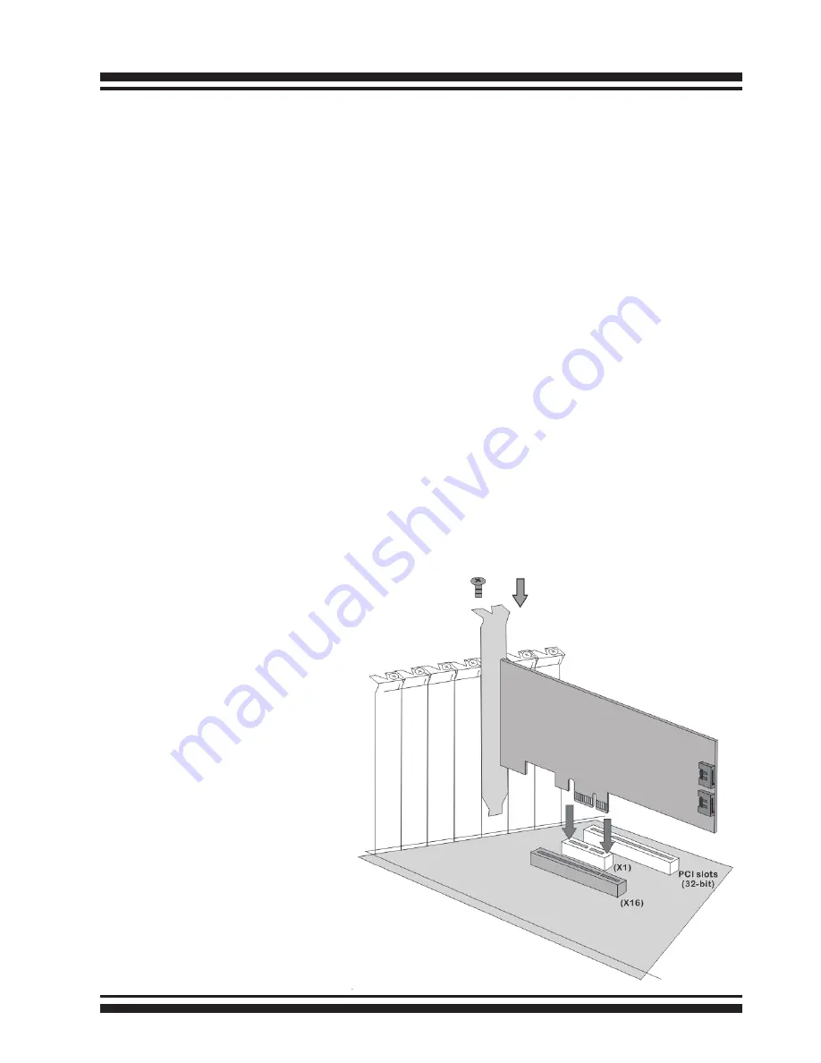
Step 3. Install the PCIe 6Gb/s SATA RAID Cards

To install the 6Gb/s SATA RAID controller, remove the mounting screw 

and existing bracket from the rear panel behind the selected PCIe 2.0 

slot. Align the gold-fingered edge on the card with the selected PCIe 

2.0 slot. Press down gently but firmly to ensure that the card is prop

-

erly seated in the slot, as shown on Figure 2-2. Then, screw the brack-

et into the computer chassis.

Figure 1, Insert into a 

PCIe slot

Summary of Contents for ARC-1203-2i

Page 1: ...ARC 1203 2 ports PCIe 2 0 to 6Gb s SATA RAID Controllers 6Gb s SATA RAID Cards Installation Guide Version 1 0 Issue Date October 2016 Website http www areca com tw...

Page 2: ...cord Remove the sys tem s cover For the instructions please see the computer system documentation Step 3 Install the PCIe 6Gb s SATA RAID Cards To install the 6Gb s SATA RAID controller remove the mou...

Page 3: ...cages or SATA drives in the computer chassis Loading drives to the drive tray if cages are installed Be sure that the power is connected to the individual drives Step 5 Connect the SATA Cable ARC 1203...

Page 4: ...activity status The global indicator connector is used by the serv er desktop system global indicator LED The following electronics schematic is the 6Gb s SATA RAID controller logical of fault activi...

Page 5: ...ault LED is off that disk is present and status is normal When the Identify Drive is selected the selected drive fault LED will blank When the fault LED is slow blinking 2 times sec that indicate disk...

Page 6: ...orms you the disk array s current operating status at a glance The LCD configuration is described in a separate manual RAID Card_LCD manual The LCD housed in a 5 inch half height or 3 5 inch canister...

Page 7: ...oxy Server The ARC 1203 2I firmware has embedded the web browser McRAID storage manager ArcHTTP proxy server will launch the web browser McRAID storage manager It provides all of the creation manageme...

Page 8: ...oller see the Chapter 6 Web Browser Based Configuration of the user manual Method 3 Front LCD Panel with Keypad Optional You can use LCD front panel and keypad function to simply cre ate the RAID volu...

Page 9: ...pose Port 14 pin header 6 SCN1 SATA Port 1 CH2 SATA III 7 SCN2 SATA Port 0 CH1 SATA III 8 D3 Fault Activity LED for CH1 Bi color DIP 9 D4 Fault Activity LED for CH2 Bi color DIP Table 1 ARC 1203 2i co...

Page 10: ...Figure 5 Connect to LCD Status Panel Figure 4 ARC 1203 2i individual Fault Activity LED for each channel drive and global indicator connector for computer case...

Reviews: