- 6 -
ARCTIV iPDU User Manual M-0010--Rev 2
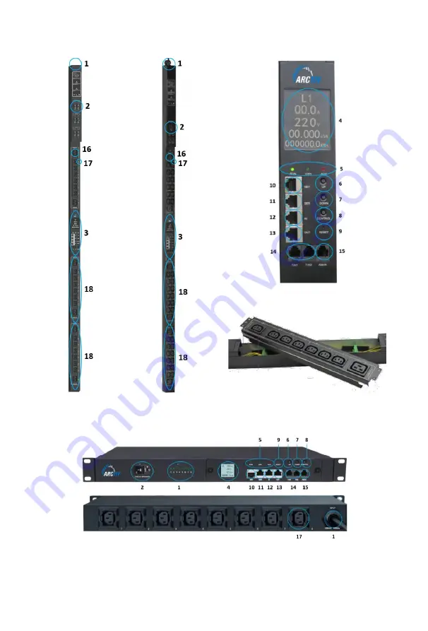
2.2 Product Pictures and Functional Diagram
Network Module
Managed PDU
(0U)
High-Density
Outlet Module
Managed PDU (1U)
Page 1: ...Logo is a registered trademark of ArcTiv Technology Co Ltd Copyright 2021 ARCTIV Technologies LLC USA All rights reserved No part of this document may be reproduced in any way without the expressed w...
Page 2: ...UNCTIONS START UP 5 2 1 Functional Overview 5 2 2 Product Pictures and Functional Diagram 6 3 HARDWARE INSTRUCTION 8 3 1 Network Module 8 3 2 System Initialization 8 3 3 Hardware Settings 9 3 4 Daisy...
Page 3: ...and technical personnel Because the PDU output module base is charged ensure proper insulation and protection during the maintenance of the equipment Before disassembling the output module please remo...
Page 4: ...et The standard features for each range include Feature Metered Input Metered Outlet Managed Monitoring of each phase Energy Power PF Voltage Current Steel Chassis Hot swap Network Module Hot swap Out...
Page 5: ...Retain the former state of each outlet after restart User defined alarm Triggered when thresholds of total current individual outlet current or temperature humidity are exceeded System default alarm...
Page 6: ...6 ARCTIV iPDU User Manual M 0010 Rev 2 2 2 Product Pictures and Functional Diagram Network Module Managed PDU 0U High Density Managed PDU 0U Outlet Module Managed PDU 1U...
Page 7: ...TROL Confirm and flip button 9 RESET Reset button 10 NET 10 100M Ethernet port 11 SER Serial port MODBUS Supported 12 IN Daisy Chain port Connect to the OUT port of previous PDU 13 OUT Daisy Chain por...
Page 8: ...and hold the control button then press RESET button to restore to factory settings UP Page Up Scroll up to the previous page DOWN Page Down Scroll down to the new page RESET RESET Button Restart syste...
Page 9: ...t power consumption of each phase 3 3 Hardware Settings Restore to factory settings Press and hold the CONTROL button to power on the PDU at the same time Or press and hold the CONTROL button and pres...
Page 10: ...the user can manage multiple PDUs from one IP address through the web interface Daisy chain schematic is as follows Ethernet Daisy Chain settings 1 Log in each PDU and configure the Work mode Master u...
Page 11: ...Serial Server connects to the Bus arbiter the RS485 port from the Bus arbiter connects to the SER port from each PDU Serial connection can support up to 32 PDUs together See figure below 1 Log on to...
Page 12: ...U OUT port to the IN port of the second PDU Connect all 32 Slave unit by the same way see Figure above Serial connection can support up to 32 PDUs together See figure as below 1 Log on to Web interfac...
Page 13: ...ds Access through the Web Interface through the following Supports browsers IE Google chrome Firefox etc SNMP V1 V2c V3 Command line interface telnet Serial communication MODBUS RTU Web Interface Open...
Page 14: ...below Input monitoring The input current voltage power energy power factor of each phase and On Off status of circuit breaker Outlet Monitoring The current power consumption and ON OFF status of each...
Page 15: ...iPDU User Manual M 0010 Rev 2 Input Threshold Settings The input voltage threshold range 0 250VAC The input current threshold range 1P 0 63A 3P 0 32A Temperature Humidity threshold range 0 400 C temp...
Page 16: ...2 Individual Outlet Threshold Settings The individual outlet current threshold range 0 16A User defined power On Off delay for individual outlets 0 10 seconds Note The low load and overload threshold...
Page 17: ...rn To Zero User can view the power consumption of individual outlet or each phase The specified power consumption can be returned to zero by clicking the Reset button The power consumption value of sp...
Page 18: ...ick the ON OFF button after the outlet to switch ON OFF the specified individual outlets Click the ON OFF button after each phase to switch ON OFF the outlets from the specified phase Click All ON All...
Page 19: ...M 0010 Rev 2 Switch Group Tick off the box from the Outlet Groups listed Select Enable from the dropdown list and click Save button By clicking the ON or OFF button you can switch on off the outlets t...
Page 20: ...list select the administrator or normal user account Next to the corresponding output bit name click the symbol to have the output bit control permission and the unsigned symbol is no output bit cont...
Page 21: ...21 ARCTIV iPDU User Manual M 0010 Rev 2 Device Management Device Settings To configure the device name LCD screen energy saving mode mute the buzzer alarm Work mode Modbus address code and baud rate...
Page 22: ...under normal work mode HTTPS SSL Mode Port is 443 by default Note These settings will take effect when PDU is restarted Network settings and modify IP address for example IP address 192 168 1 163 fac...
Page 23: ...m the DHCP drop down list and click Save to enable it After restarting the software the device will receive the IP automatically IP can be viewed from the LCD screen Note When DHCP is On the device au...
Page 24: ...read community and write community The default Read community and Write community is public and private respectively Trap address can set 2 trap addresses Fill in the trap address of SNMP management...
Page 25: ...SMTP service including SMTP account password SMTP server working mode SMTP SMTPS and e mail recipients up to 5 recipients then Click Save SMTP settings will take effect when PDU is restarted SMTP test...
Page 26: ...ngs Telnet Select Enable or Disable Enable by default and save make sure to restart the software after modification Telnet account and password is the same one used for login Telnet port is 23 Note te...
Page 27: ...gs Local time calibration Click Time Acquisition to synchronize the iPDU system time to the local machine Network time calibration Click Time Acquisition to synchronize the iPDU system time and date t...
Page 28: ...ount Select the user account from the user list and click Delete Note The maximum length for user name and passwords is 10 characters the user name and password exceeds the maximum of 10 characters wi...
Page 29: ...e of the log Every page display 30 logs and maximum support to 10 pages the initial pages will be deleted when over 10 pages To delete the log click Delete on the web page at the prompt check OK to de...
Page 30: ...estore to factory settings from the system command drop down list SNMP access This software supports SNMP V1 V2C and V3 a MIB file can be provided at customer s request User can view the power informa...
Page 31: ...ly Telnet does not support the Daisy chain connection user can only access and manage the Master unit To open the Telnet client by Start Run command enter Telnet in the input box and click OK Enter th...
Page 32: ...ata including current voltage power power factor and power consumption on each phase Command line format PHASE as shown below OUTPUT Command Use the OUTPUT command to view the current power power cons...
Page 33: ...old Command line format SENSOR see figure below ON OFF Command Use the ON OFF command to switch On Off the individual outlet outlets from each phase or all outlets Command line format ON OFF index ope...
Page 34: ...h Off the outlet 1 OUTPUT command can switch ON OFF one outlet at one time GROUP Enter command line on group 1 to switch on outlet from branch circuit 1 Enter command line off group 1 to switch off ou...
Page 35: ...nd to logout the Telnet command line as shown below HELP Command Use the HELP command to shows general help as shown below MODBUS RTU access Use two wire RS 485 serial communication port for serial ac...
Page 36: ...8 24 36 42 Outlets Output Voltage 1P 100VAC 240VAC 50 60 Hz Max Output Current 16A 32A Max Phase Current 16A 32A Control Ports NET Port 1xRJ45 Ports Daisy Chain Port 2xRJ45 Ports SER Port 1xRJ45 Ports...
Page 37: ...ng 0U Tool less button 1U EIA Rails Case Color Black Accessories included Installation Bracket 1 Set Network Cable 2M Blue Serial Cable 2M White User Manual 1 set CD Optional Sensor Temperature Humidi...
Page 38: ...arranty Problems caused because of improper maintenance Problems caused because of unauthorized change modification or improper use The devices are not used in the rated physical environment Problems...