

OWNER’S MANUAL: EDGE
-SERIES
–
SWING GATE WALL MOUNT CABINETS
8
© 2018 ArcTiv Technologies, LLC
ATSGWM-MANUAL-01
ACCESSORY AND EQUIPMENT INSTALLATION
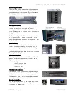
Mounting Rail Adjustment
The cabinet includes 4 mounting rails that have square
holes for mounting rack equipment. The rails are pre-
installed but can be easily adjusted to match your
equipment depth by the following steps:
•
Each rail is connected to the enclosure with 2
screws: 1 in the upper corner and another in the
lower corner. Using a Phillips-head screwdriver,
remove the screws that fasten the rails to the
enclosure.
•
Slide the mounting rails to the desired depth and
reattach them using the removed screws.
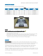
To install equipment, use the included cage nuts and other
hardware.
Warning: Be sure to have the enclosure in its final position
on the floor before mounting any equipment inside.
Revi-
Ring™ Vertical D
-Ring Manager Installation
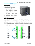
ArcTiv’s
patented Revi-
Ring™ Vertical D
-Ring Managers allow for high-density organization of network and power cables in the
cabinet. They attach directly to the mounting rails via 2 screws and can be reversed to allow the greatest mounting rail depth. To use
the full benefit of the reversed Revi-
Ring’s, move the front
and/or rear mounting rails to the 1
st
or 2
nd
mounting position and use a
horizontal brush strip or lacing bar to support the front-side network cables. The bundle can then be routed through the Revi-
Ring™
D-Ring without compromising any rack space. See the figure below on the installation process for front and reverse mounting.
The individual D-Rings can rotate in order to allow a smooth transition of cables from the horizontal manager to the vertical channel.
This is easily completed by slightly loosening the mounting screw with a Philips screwdriver, rotating the D-Ring and then tightening to
the desired position.


