T3 can function either as an electronic lock-out relay or as a trip relay. When T3 is configured as an
electronic lock-out relay, its type is normally closed (NC) and it holds its position until it receives a
manual reset command or until auxiliary power is lost. When re-applying the auxiliary power supply, the
electronic lock-out relay returns to the same contact condition it had prior to the power loss. This
normally closed relay output can also be used for tripping contactor-controlled devices. If the
application so requires, T3 can also be ordered as normally open (NO) from the factory. This choice is
specified when ordering this unit.
8.1.2. High-speed output(s)
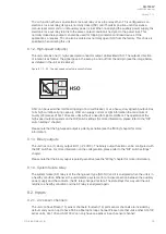
The unit contains one (1) high-speed semiconductor output, abbreviated HSO. The output’s direction
of rotation is as follows: the signal goes in the even pin and out from the odd pin (see the image below,
as detailed in the unit’s side sticker).
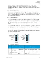
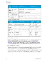
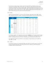
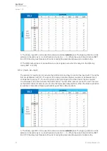
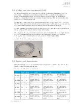
Figure. 8.1.2. - 20. The high-speed output's direction of rotation.
HSO can be used either for direct tripping of a circuit breaker, or as a heavy-duty signaling output. Due
to its high current-carrying capacity, HSO can supply current or light information to a maximum of
twenty (20) pieces of AQ-100 series units without a need for signal amplifiers. The operation of the
high-speed output depends on the DIP switch settings (for more information, please refer to the “DIP
switch settings” chapter).
Please note that the high-speed output is polarity-sensitive (see the "Wiring" chapter for more
information).
8.1.3. Binary outputs
The unit has one (1) binary output: BO1 (+24 VDC). The binary output function can be configured with
the DIP switches. For more information on the configuration, please refer to the "DIP switch settings"
chapter.
Please note that the binary ouput is polarity-sensitive (see the "Wiring" chapter for more information).
8.1.4. System failure relay
The system failure (SF) relay is of the change-over type (NO/NC) and it is energized when the unit is in
a healthy condition. Whenever the unit detects a system error or a disconnection between the auxiliary
power supply and the contacts, the SF relay changes its state. The state stays this way until the unit
returns to a healthy condition and the SF relay is energized again.
8.2. Inputs
8.2.1. Arc sensor channels
The unit can have fifteen (15) sensor channels: fourteen (14) point sensor channels are included by
default, and you can opt to have S5 be a fiber optic loop channel. Please note that unlike other AQ-100
series units, AQ-103 and AQ-103LV can only have one sensor in each sensor channel!
A
AQ
Q-103L
-103LV
V
Instruction manual
Version: 1.00
© Arcteq Relays Ltd
32

