7
918 series Powerig Hydraulic Units (HK786
)
Checking & Adjusting Pressures
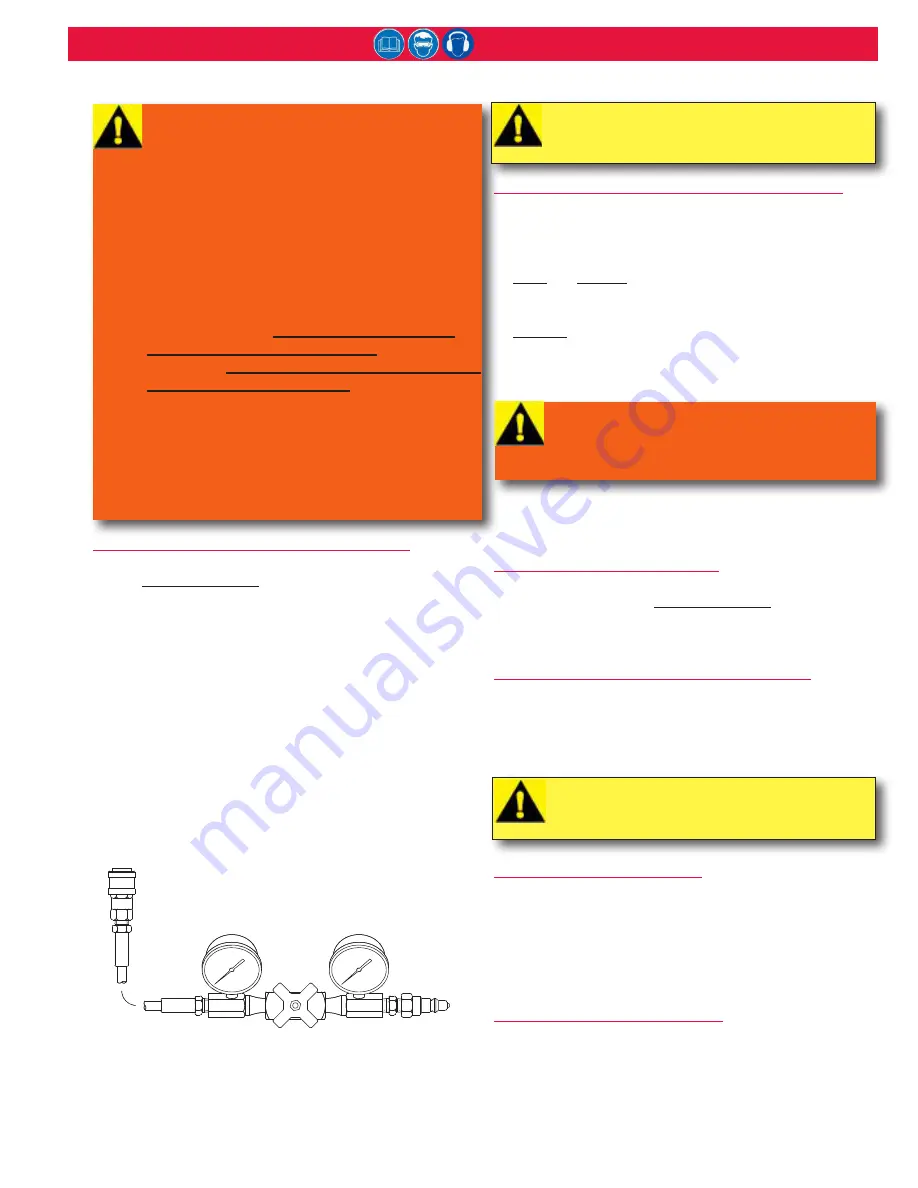
PREPARATION FOR USING GAUGE T-124833CE
If necessary, prime and bleed the POWERIG
®
Hydraulic Unit.
See the
P
rEParation
for
u
SE
section of this manual.
NOTE:
Check each tool's pressure separately.
1. Turn OFF the POWERIG. Connect the male coupler of
gauge to PULL pressure female coupler of Powerig.
2. Connect female coupler of gauge to RETURN pressure
male coupler of Powerig.
3. Turn needle valve of T-124833CE all the way out.
4. Install auxiliary electric switch and control cord assembly
(P/N
113056
) in the control cord socket of the tool port
being checked, or use the trigger of the tool connected
to the ports being checked. Fluid will be directed out the
PULL pressure port when the switch is pressed. Connect
the Powerig to the primary power source and turn it ON.
CHECKING OUTPUT PRESSURES USING T-124833CE
1. Close the valve (turn handle clockwise). Press and hold
auxiliary trigger switch. Read the PULL pressure on right
gauge. Release trigger switch.
2. Open valve by a few counterclockwise handle turns.
3.
Press
and
Release
auxiliary trigger switch to set the unit’s
internal valve. Hydraulic fluid is directed out RETURN
pressure port.
4.
SLOWLY
close the valve. The pressure will rise, and then
sharply drop. Read the RETURN pressure on the left gauge
just before the pressure drops.
5. Open the valve. Turn OFF the Powerig.
6. Disconnect auxiliary trigger, then pressure setting gauge.
7. Refer to installation tool’s instruction manual for specific
PULL and RETURN pressures.
ADJUSTING OUTPUT PRESSURES
The POWERIG Hydraulic Unit should be prepared for
operation as described in
P
rEParation
for
u
SE
.
Use Gauge
T-124833CE to check pressures before and after adjusting
PULL and RETURN pressures.
ADJUSTING COMBINATION VALVE P/N 119740
The 918 and 918-5 POWERIG Hydraulic Units are equipped
with valves that can be set at specific PULL and RETURN
pressures (see the applicable instruction manual for your
tool). There is a socket-head screw to adjust PULL pressure
and a different one to adjust RETURN pressure. See Figure 7.
PULL PRESSURE ADJUSTMENT
Use 5/16” hex key for PULL pressure adjusting screw.
Turn adjusting screw clockwise to increase pressure.
b. Turn adjusting screw counterclockwise to decrease
pressure.
c. Check resulting PULL pressure setting with Gauge
T-124833CE.
RETURN PRESSURE ADJUSTMENT
Use 5/16” hex key for RETURN pressure adjusting screw.
a. Turn adjusting screw clockwise to increase pressure.
b. Turn adjusting screw counterclockwise to decrease
pressure.
c. Check resulting RETURN pressure setting with Gauge
T-124833CE.
WARNINGS:
Turn OFF the Powerig prior to connecting
or disconnecting tools. If it is necessary to
connect or disconnect a tool while the unit
is running, use the following procedure for
maximum safety.
Connect tool’s hydraulic hoses to unit before
connecting tools switch control cord to unit.
If a malfunctioning cord switch is connected
first, hydraulic unit may begin to cycle
unexpectedly. Unexpected cycling may lead
to serious injury. When connecting hoses,
switch MUST be connected last. Just as
important: When disconnecting hoses, switch
MUST be disconnected first.
Maximum PULL pressure is 8400 psi (648
bar). Refer to specific tool instruction manual
for PULL and RETURN pressures for Huck
installation equipment. Severe personal injury
may occur if excessive pressures cause
violent failure of equipment.
WARNING: Turn OFF the hydraulic unit.
Accidental cycling of the unit may cause
severe injury when disconnecting couplings.
Fluid may unexpectedly spray.
CAUTION: The following check must be
completed quickly. Sustained high pressure
will cause premature wear on the unit.
CAUTION: Whenever possible, set Powerig
pressures to the lowest recommended
pressure to minimize wear on the equipment.
T-124833CE
Pressure Gauge
Summary of Contents for 918 Series
Page 2: ...2 918 series Powerig Hydraulic Units HK786 ...
Page 14: ...14 918 series Powerig Hydraulic Units HK786 918 918 5 Hydraulic Diagram Figure 5 ...
Page 15: ...15 918 series Powerig Hydraulic Units HK786 Typical Hose and Control Cord Hook up Figure 6 ...
Page 22: ...22 918 series Powerig Hydraulic Units HK786 Electrical Control Panel Wiring Figure 13 ...


