7
2624 & 2630 series Hydraulic Installation Tools (HK1052)
See
Specifications
for fluid type. Dispose of fluid in
accordance with local environmental regulations. Recycle
steel, aluminum, and plastic parts in accordance with local
lawful and safe practices.
PREVENTIVE MAINTENANCE
The operating efficiency of your tool is directly related
to performance of the entire system. Therefore, a regular
schedule of “preventive” maintenance of the tool, nose
assembly, hydraulic hoses, trigger and control cord,
and Powerig
®
hydraulic power source will ensure your
tool’s proper operation and extend its life. Also see
Troubleshooting
, parts lists, and
Disassembly
and
Assembly
procedures in this manual.
POWERIG
®
HYDRAULIC POWER SOURCE
Maintenance instructions and repair procedures are in the
appropriate Powerig hydraulic power source Instruction
Manual.
SYSTEM INSPECTION
An effective maintenance program includes scheduled
inspections of the system to detect minor troubles that
can be quickly and easily
corrected. Huck recommends
that you:
Inspect the tool and nose for external damage
.
Verify that hoses, fittings, couplings, and electrical
connections are secure and free of leaks.
Inspect hydraulic hoses for signs of damage. Replace if
necessary.
Inspect the tool, hoses, and Powerig during operation to
detect abnormal heating, leaks, or vibration
.
TOOL
At regular intervals, depending on use, replace all O-rings
and Back-up rings in the tool. Spare Parts Kits should be
kept on hand. Inspect cylinder bore, piston, piston rod,
and unloading valve for scored surfaces, excessive wear,
and damage; replace as necessary
.
NOSE ASSEMBLY
Daily cleaning of the nose assembly is recommended.
This can usually he accomplished by dipping the nose
assembly in mineral spirits, or other suitable solvent, to
clean the jaws and wash away metal chips and dirt. If a
more thorough cleaning or maintenance is necessary,
disassemble the nose assembly. Use a sharp pointed
“pick” to remove embedded particles from the pull
grooves of the jaws
.
Maintenance
Stickers on the tool must be replaced when the cylinder is replaced, or if they become worn, damaged, or
unreadable. Refer to
Sticker Locations
in this manual for information on sticker locations and part numbers.
CAUTIONS:
Consult the Material Safety Data Sheet (MSDS)
before servicing tool.
Keep foreign matter out of the hydraulic
system. Keep separated parts away from dirty
work surfaces.
Dirt and debris in hydraulic fluid causes valve
failures in tool and Powerig® hydraulic power
source.
Check components drawings in this manual
for correct orientation of polyseals and dump
valve.
Do not use Teflon
® tape on pipe threads. Tape
can shred, resulting in malfunctions. Apply
Parker Threadmate, Loctite 567, or Slic-tite
stick to male pipe threads per manufacturer’s
instructions.
Always replace seals, wipers, and Back-up rings
when the tool is disassembled for any reason.
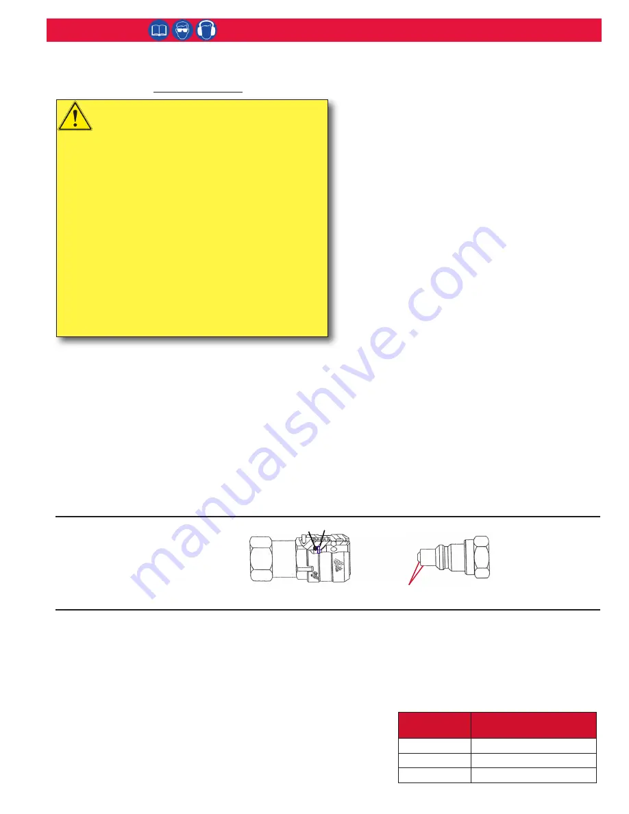
Hydraulic Couplings
504438 O-ring
501102 Back-up Ring
110439
Female
Connector
110438
Male
Connector
Use a fine India stone to remove any nicks or burrs from these
areas to prevent damage to O-ring of Female Connector.
Assembly of NPTF Threaded Components
AIR FITTINGS
1) Apply TEFLON® stick to male threads which do not have pre-applied sealant
per manufacturer’s recommendations. (Proceed to All Fittings step 2)
HYDRAULIC FITTINGS
1) Apply Threadmate
™
to male and female threads which do not have pre-applied
sealant per manufacturer’s recommendations. (Proceed to All Fittings step 2)
ALL FITTINGS:
2) Tighten to finger-tight condition.
3) Wrench tighten to 2-3 turns past finger-tight condition.
4) Final thread engagement can be checked (optional) by measuring the
dimension from the flange of male fitting to the end of the thread
before assembly and subtracting the distance under the flange after
assembly.
Thread Size Final thread engagement
at full make-up
1/8-27 NPTF
.235 inch
(.59 cm)
1/4-18 NPTF
.339 inch
(.86 cm)
3/8-18 NPTF
.351 inch
(.89 cm)


