


244BT Pneudraulic Installation Tool (HK1113)
7
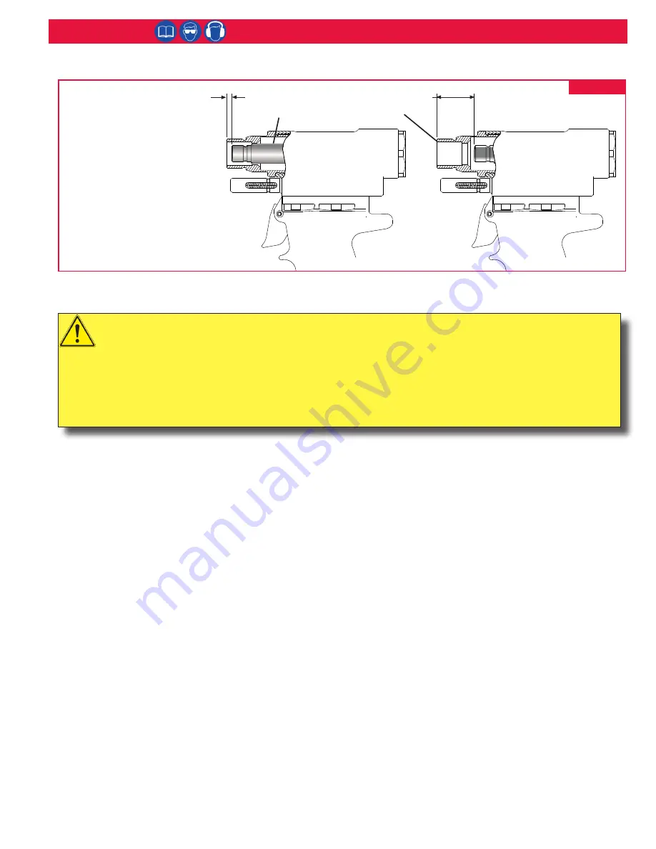
Measuring Tool Stroke
A
B
Nose
Adapter
Hydraulic
Piston
1. Measure distance “A”
from face of Hydraulic
Piston to face of Nose
Adapter. This distance
should approximately
equal .173 inches.
2. Cycle tool and hold
piston back by keeping
the trigger pressed.
Measure distance “B” as
above.
3. STROKE = B - A
(B minus A)
Maintenance
NOTES: See
S
pecificationS
for fluid type. Dispose
of fluid in accordance with local environmental
regulations. Recycle steel, aluminum, and plastic parts
in accordance with local lawful and safe practices.
GENERAL
1. The efficiency and life of any tool depends upon
proper maintenance. Regular inspection and correction
of minor problems will keep tool operating efficiently
and prevent downtime. The tool should be serviced
by personnel who are thoroughly familiar with how it
operates.
2. A clean, well lit area should be available for servicing
the tool. Special care must be taken to prevent
contamination of pneumatic and hydraulic systems.
3. Proper hand tools, both standard and special, must be
available.
4. All parts must be handled carefully and examined for
damage or wear. Always replace Seals, when tool is
disassembled for any reason. Components should be
disassembled and assembled in a straight line without
bending, cocking, or undue force. Disassembly and
assembly procedures outlined in this manual should
be followed.
5. Service Parts Kit 244BTKIT includes consumable
parts and should be available at all times. Other
components, as experience dictates, should also be
available.
DAILY
1. If a Filter-Regulator-Lubricator unit is not being used,
uncouple air disconnects and put a few drops of
Automatic Transmission Fluid or light oil into the air
inlet of the tool. If the tool is in continuous use, put a
few drops of oil in every two to three hours.
2. Bleed the air line to clear it of accumulated dirt or
water before connecting air hose to the tool.
3. Check all hoses and couplings for damage or air leaks,
tighten or replace if necessary.
4. Check the tool for damage or air/hydraulic leaks,
tighten or replace if necessary.
5. Check the nose assembly for tightness or damage,
tighten or replace if necessary.
6. Check oil level in tool reservoir, replenish if necessary.
WEEKLY
1. Disassemble and clean nose assemblies and
reassemble.
2. Check the tool and all connecting parts for damage or
oil/air leaks, tighten or replace if necessary.
CAUTIONS:
Consult MSDS before servicing tool.
Keep dirt and other material out of hydraulic system.
Separated parts most be kept away from dirty work surfaces.
Always replace seals, wipers, and back-up rings when tool is disassembled for any reason.
Do not use TEFLON® tape on pipe threads. Pipe threads may cause tape to shred resulting in tool
malfunction. (Threadmate™ is available from Huck in a 4oz. tube as part number 508517.)
Dirt/debris in hydraulic fluid causes Dump Valve failure in Tool and in Powerig Hydraulic Unit’s valves.
Figure 1


